


36
36
3-90-30007480
Hearth and Home Technolgies • Oxford Direct/Natural Vent Installation Manual_R3 • 02/19
I. Lighting Troubleshooting
(Continued)
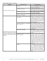
IntellifireTM Ignition System
Symptom
Possible Cause
Corrective Action
Pilot won’t light. The ignitor/module makes
noise, but no spark.
Incorrect wiring.
Verify “S” wire (white) for sensor and “I” wire
(orange) for ignitor are connected to correct
terminals on module and pilot assembly.
Loose connections or electrical shorts in
the wiring.
Verify no loose connections or electrical
shorts in wiring from module to pilot assembly.
Verify connections underneath pilot assembly
are tight; also verify connections are not
grounding out to metal chassis, pilot burner,
pilot enclosure, mesh screen if present, or
any other metal object.
Ignitor gap is too large.
Verify gap of igniter to right side of pilot hood.
The gap should be approximately .095 in.
(2.41 mm) to .135 in. (3.43 mm).
Module.
Turn ON/OFF rocker switch or wall switch to
OFF position. Remove ignitor wire “I” from
module. Place a grounded wire about 3/16
in. (5 mm) away from “I” terminal on module.
Place ON/OFF rocker switch or wall switch in
ON position. If there is no spark at “I” terminal
module must be replaced. If there is a spark
at “I” terminal, module is fi ne. Inspect pilot
assembly for shorted sparker wire or cracked
insulator around electrode. Replace pilot if
necessary.
Pilot won’t light, there is no noise or spark.
No power or power supply installed
incorrectly.
Verify that power supply is installed and
plugged into module. Check voltage of power
supply under load at spade connection on
module with ON/OFF switch in ON position.
Acceptable readings of a good power supply
are between 3.2 and 2.8 volts AC.
A shorted or loose connection in wiring
configuration or wiring harness.
Remove and reinstall the wiring harness
that plugs into module. Verify there is a tight
fit. Verify pilot assembly wiring to module.
Remove and verify continuity of each wire
in wiring harness. Replace any damaged
components.
Improper wall switch wiring.
Verify that 110/VAC power is “ON” to junction
box.
Module not grounded.
Verify black ground wire from module wire
harness is grounded to metal chassis of
appliance.
Module.
Turn ON/OFF rocker switch or wall switch to
OFF position. Remove ignitor wire “I” from
module. Place ON/OFF rocker switch or wall
switch in ON position. If there is no spark
at “I” terminal module must be replaced. If
there is a spark at “I” terminal, module is fine.
Inspect pilot assembly for shorted sparker
wire or cracked insulator around electrode.