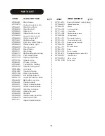
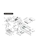
Health Master HM-T3200 Owner'S Manual Download Page 16


14

EXPLODED DRAWING


H11 


AF1 


F08 


AF2 


F14 


F11 


AF3 


F13 


F12 


AJ 


AJ 


AX 


H08 

H02 


H09 


H12     
BQ 


H04 


H13 


H20 


H01 

AN 

J03 


J23 


B23 


B39 

CP 


B22 


J15 

AS 

J13 

AX 

H10 

J28 


J22 


J09 

AO 

AG1 

AG1 


AU 

AD1 

CQ 

AC 

BN 

AS 


B34 


AC 

AG 

C16 

AS 


AJ 


AG 

C18 


B24 


AT 

C11 


AD 


J01 


B19 


K03 


AE1 

AB 

J02 


AH 

AG 


AL 

AM 


AJ 


AC 


B28 


AO 


AC 

AG 


J08 

AL 

CJ 

J16 


AG 

AB1 

AL 


AI 


B27 


J17 


AJ 


J18 


B21 


AG 


B33 

AC1 

BN 


AL   

C13 

C14 

 
E04 

E07 


K01 


AR 

B25 

K02 


CO 

B26 

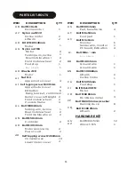
Summary of Contents for HM-T3200

Page 1: ......

Page 2: ...ING ASSEMBLY p4 ASSEMBLY DRAWING p5 COMPUTER OPERATIONS p6 p7 Control panel function control panel operation BELT ADJUSTMENT p8 CARE MAINTENANCE p9 LUBRICATION MAINTENANCE P10 TROUBLE SHOOTING p11 PAR...

Page 3: ...age of 35 or persons with pre existing health problems Read all instructions before using any fitness equipment We assume no responsibility for personal injury damage sustained by or through the use o...

Page 4: ...se is reflected in your heart rate Exercise must be sufficiently rigorous to strengthen your heart muscle and condition your cardiovascular system Only your doctor can prescribe the target training he...

Page 5: ...t Feel the stretch up your right side Repeat this action with your left arm Toe touches Slowly bend forward from your waist letting your back and shoulder relax as you stretch toward your toes Reach d...

Page 6: ...picture showing fold up the treadmill 3 Hold on roller cover by two hands and lean back the treadmill move the treadmill forward as the picture showing Failure to follow this procedure may result in s...

Page 7: ...incline in percent of grade in 1 increments MODE Enter programs selection enter time setting push 3 seconds for scanning ONE TOUCH SPEED 6 8 10 12 Used to reach ideal speed ONE TOUCH INCLINE 0 5 10 15...

Page 8: ...sert the right console mast into the base frame secure the right console mast with four M8X15mm bolts usingAllen wrench Do not tighten the bolts A connect the upper console wire to lower console wire...

Page 9: ...LT TURN BOTH BOLTS COUNTER CLOCKWISE THE SAME NUMBER OF TURNS CENTERING THE RUNNING BELT When you run you may push off harder with one foot than with another The severity of the deflection depends on...

Page 10: ...operation to use this treadmill especially for professional runner ONE TOUCH INCLINE There is one set of ONE TOUCH INCLINE control panel on the console overlay for user to select the ideal incline ONE...

Page 11: ...utes per time 3 4 times per week For lubrication you can contact your dealer CLEANING Perspiration should be wiped from the console and treadmill surface after your workout You should wipe down your t...

Page 12: ...W TO SPRAY SILICONE ON DECK A Find the silicone bottle It is located in the hardware kit package included with this treadmill B Find a straw and put it onto the silicone bottle as the drawing shows C...

Page 13: ...om is current overload protection And show E1 error 1 on monitor E1 is to inform the runner to examine your treadmill by yourself to avoid the damage happened on treadmill The runner can follow the be...

Page 14: ...8 B39 ST08 AC1 ST03 C11 ST08 C13 Running deck Base frame Foot step Mobile wheel housing 1 ST06 J17 1 ST06 J18 1 ST01 J19 2 ST08 J22 On off switch 1 Fuse 1 Core motor 1 Fixing bracket controller 1 ST01...

Page 15: ...round wire 1 BN Bolt M10X60mm Motor 1 Lift arm 2 AI Nut M4 Upper motor cover 4 CA Incline motor 1 Bolt M5X55mm AJ Self tapping screw M4X15mm Upper motor cover 4 Foot step 1 CJ Bolt M8x125MM EZ button...

Page 16: ...H20 H01 AN J03 J23 B23 B39 CP B22 J15 AS J13 AX H10 J28 J22 J09 AO AG1 AG1 AU AD1 CQ AC BN AS B34 AC AG C16 AS AJ AG C18 B24 AT C11 AD J01 B19 K03 AE1 AB J02 AH AG AL AM AJ AC B28 AO AC AG J08 AL CJ...

Reviews: