HDT Camfire MV60S-EU Operation And Maintenance Manual Download Page 1


MV60-EU Series Heaters, 220 VAC, 50-60 Hz 
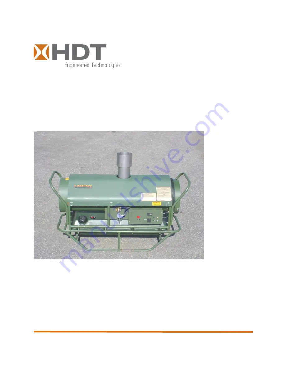
 

SHELTER HEATER 
60,000 BTU Multi-fuel Shelter Heater


Operation and Maintenance Manual 


HDT 

–Tactical Systems Business Unit 

30525 Aurora Rd 
Solon, Ohio 44139-2795 
Tech Support: (800) 684-6111  
www.hdtglobal.com 


MANUAL PART NUMBER: 53858 
REVISION 3 

– 26APRIL2011 

Summary of Contents for Camfire MV60S-EU

Page 1: ...LTER HEATER 60 000 BTU Multi fuel Shelter Heater Operation and Maintenance Manual HDT Tactical Systems Business Unit 30525 Aurora Rd Solon Ohio 44139 2795 Tech Support 800 684 6111 www hdtglobal com MANUAL PART NUMBER 53858 REVISION 3 26APRIL2011 ...

Page 2: ...THIS PAGE INTENTIONALLY LEFT BLANK ...

Page 3: ...xchanger temperatures which can cause the heat exchanger to fail allowing dangerous Carbon Monoxide gas to enter the shelter Failure to follow these instructions could cause serious injury or death WARNING FIRE EXPLOSION Use only Kerosene Diesel or Number 1 Fuel Oil or JP8 can be used for extreme cold conditions Never burn gasoline naphtha paint thinners alcohol or other volatile fuels Fill fuel t...

Page 4: ...or death may occur if personnel come in contact with high voltage lead WARNING FIRE EXPLOSION Do not operate heater without output duct P N CAH 1015 properly installed Ensure hot air outlet is at least 1 5 meters from combustible materials Ensure ducts outlet and inlet are free from obstructions and sharp bends ALWAYS REMOVE STORAGE PLUG CAH 126 1 BEFORE OPERATING HEATER WARNING HOT SURFACES Parts...

Page 5: ...NING CARBON MONOXIDE POISONING The heat exchanger must be inspected annually by qualified service personnel for leaks which could allow dangerous carbon monoxide gas to enter the shelter Failure to due so could cause severe injury or death ...

Page 6: ... Final Checks Before Operation 33 2 7 Starting and Operating the Heater 33 2 7 1 Starting the Heater 33 2 8 Refueling During Operation 34 2 9 Shutting Down the Heater 34 2 10 Preparing for Movement or Storage 34 2 10 1 Preparing for Movement 34 2 10 2 Preparing the Heater for Storage 35 3 CAMFIRE Troubleshooting 38 3 1 Introduction 38 3 2 Operator Level Troubleshooting 38 3 3 Safety Control Operat...

Page 7: ...spect Test 63 4 4 4 Checking Motor Starting Circuits Test 65 4 4 5 Fan Service 67 4 4 6 Sediment strainer Service 68 4 4 7 Burner Head Service Clean 69 4 4 8 Air Pump Repair Inspect Test Repair 73 4 4 9 Safety Control Circuit Testing Test Clean 81 4 4 10 Photocell Test 85 5 Illustrated Parts Listing 88 6 Schematics and Wiring Diagrams 106 7 Alphabetical Index 108 ...

Page 8: ...102 Figure 6 1 Camfire Heater Wiring Diagram 106 Figure 6 2 Camfire MV60 Fuel Schematic 107 Table of Tables Table 1 1 CAMFIRE Heater Warning Labels and Data Plates 16 Table 1 2 Camfire Heater Specifications 19 Table 2 1 Flexible Duct Usage vs Outside Temperature 27 Table 2 2 Extension Cord Size Requirements 32 Table 3 1 Operator Level Malfunction Symptom Index 39 Table 3 2 Operator Level Troublesh...

Page 9: ...Operation and Maintenance Manual 9 Chapter 1 System Overview Description and Principles of Operation ...

Page 10: ...he tank by siphon action and carries it into the combustion chamber Filters protect the fuel system prior to the fuel entering into the spray nozzle The electrical control system is protected by a push button type circuit breaker A safety control unit connected to a photoelectric cell shuts down the heater if a flame is not detected in the combustion chamber after start up It also has two diagnost...

Page 11: ... and hour meter Exhaust Stack Extension The exhaust stack extension is installed in the exhaust outlet on the top of the heater and acts to direct the combustion gases away from the heater An internal screen in the exhaust stack extension acts as a spark arrester Inlet and outlet ducts 15 foot flexible ducts connect to the shelter duct tunnels and circulate heated and unheated air through the shel...

Page 12: ...at Burner assembly The burner assembly is where all combustion occurs within the Camfire heater Atomized fuel is mixed with air and ignited by the spark plug to create the heat circulated through the shelter Power cable A 6 foot long AC power cable that connects the heater with a 220 VAC power source The power cable is wrapped around the inlet duct adapter ...

Page 13: ... until the set point is reached Roll bars handles and local transport wheels Handles are located at either end of the heater and permit the heater to easily be moved into position Roll bars are located around the heater and act to protect the heater from damage Local transport wheels optional accessory permit the heater to be rolled into position Local transport wheels are an optional accessory Se...

Page 14: ... selects AUTO or MANUAL heat mode 3 Pilot Light Indicates that power is supplied to the heater 4 Thermostat Jack Permits the connection of the remote thermostat assembly 5 Hour meter Displays the total number of operating hours for the heater 6 Circuit Breaker Protects the heater against circuit overload 7 View Port Allows the user to view the diagnostic LEDs for troubleshooting and repair Figure ...

Page 15: ...erature Control Placed inside the shelter being heated permits the operator to set the desired temperature of the shelter 2 Temperature Sensing Coil Located on the top of the remote room thermostat monitors the temperature of the shelter Figure 1 2 Remote Room Thermostat 1 2 ...

Page 16: ...es WARNING Label or Data Plate Location Description Located on the side of the heater the data plate provides pertinent data including Model Number and Serial Number Located on the control panel identifies the circuit breaker See section on controls and indicators Located near the fan compartment warns user of electrical shock potential inside fan compartment Located on fan assembly label identifi...

Page 17: ...tifies power switch Located inside heater near air pump identifies pressure adjustment screw Located inside heater near burner assembly identifies pressure gauge Located on end plug at end of heater identifies the fact that the cap must be removed before operation Also informs user of accessories stored inside end plug Located on control panel identifies Reset switch ...

Page 18: ... the ignition transformer Located on control panel alerts user that only 220VAC power should be used Located near fuel filler cap on side of heater warns user against the use of naptha and identifies all approved fuels Located near duct connections at end of heater Warns user that only approved flexible ducts rated for temperatures of 300 degrees F or higher can be used 220 VAC ...

Page 19: ...ume CFM Approximate 600 Other Ratings Current starting 3 5 AMPS Current running 2 2 AMPS Voltage 220 VAC Frequency 50 60 Cycles Fan Pump Motor 1 4 HP Air Pump Pressure 5 0 PSI Fuel Nozzle Meter Size 0 65 GPH Spray Angle 80 DEGREES Fuel Kerosene DF1 DF2 Fuel Oil JP8 Only Tank Capacity 8 5 GAL Flexible Ducts 2 12 inch diameter 15 ft Length Dimensions Without Stack Extension W15 L46 H25 Weight Withou...

Page 20: ...gnition system consists of a transformer and spark plug The transformer increases the input voltage to a very high potential that causes an arc to be drawn between the electrodes of the spark plug The arc is used to ignite the fuel and air mixture within the combustion chamber Control System The safety control circuit consists of a duct over heat switch a light sensitive photocell and a safety con...

Page 21: ... and cause the heater to shut down When the air cools the thermostat contacts close and the heater recycles A duct over heat switch is located at the outlet end of the heater This switch will shut down the heater if the duct temperature exceeds approximately 275 degrees F Figure 1 3 System Operational Diagram simplified for clarity ...

Page 22: ...Operation and Maintenance Manual 22 ...

Page 23: ...Operation and Maintenance Manual 23 Chapter 2 Setup and Operation of the CAMFIRE Heater ...

Page 24: ...Operation and Maintenance Manual 24 ...

Page 25: ...en unpacking the heater remove all protective material covering the heater and remove the unit from the shipping pallet 2 1 2 Installing the Exhaust Stack Extension The exhaust stack extension is wrapped in foam and packaged to the side of the heater Unwrap the exhaust stack extension and install on the top of the heater by engaging the exhaust stack extension into the exhaust port at the top of t...

Page 26: ...carry the CAMFIRE heater when lifting or lowering the unit Be sure to lift with legs not back to prevent injury The CAMFIRE heater site location will be dictated by the location of the shelter since the heater inlet 1 and outlet 2 ducts must be able to reach the shelter duct tunnels 3 see photo next page The heater site must be as level as possible and free of combustible material e g dried twigs ...

Page 27: ...length and 12 inches in diameter connect to the inlet and outlet ends of the heater and move air from the interior of the shelter through the heater and back to the interior of the shelter In conditions where the outside ambient temperature is above freezing only the heated air supply duct is used In this way the heater draws unheated air from the outside Operating the heater without input ducting...

Page 28: ...tlet end 6 of the heater as indicated by the label Heated Air Outlet on the upper housing assembly Make sure about 12 inches of the outlet end 4 protrude into the shelter 7 so that the air can be directed away from the inlet properly Secure the shelter duct tunnel tie straps Do not secure the straps so tightly that the air flow within the duct is restricted Attach the end of the duct with the J sl...

Page 29: ...Operation and Maintenance Manual 29 Re circulation mode Outside air mode see next section 7 1 2 5 3 4 6 8 9 14 3 15 12 Duct inside shelter Duct outside shelter ...

Page 30: ...result in fire or explosion 2 4 Before Operation Preventative Maintenance Checks and Services PMCS Perform the Before Operation PMCS on all CAMFIRE heater components as outlined in section 4 2 prior to preparing the heater for use All scheduled maintenance must be performed on the heater and its associated equipment prior to use 2 5 Fueling 2 5 1 Fueling the Internal Tank MV60S EU MV60T EU Remove ...

Page 31: ...t fully counter clockwise so that it does not turn on unexpectedly while setting up Route the thermostat control into the shelter and hang from a convenient location Be sure to position the control so that it is not in the direct path of the heated air outlet or the cold air at the entrance to the shelter You may need to try several locations in the shelter before a suitable location is found To u...

Page 32: ...wer cable 2 and connect the male end of the power cable to a 220 VAC 50 60 cycle single phase power source with GFCI If an extension cord is required ensure that it is a three wire cord and of adequate size as listed in the following table Table 2 2 Extension Cord Size Requirements LENGTH OF CORD WIRE SIZE AWG 100 ft NO 14 200 ft NO 12 300 ft NO 10 400 ft NO 8 450 ft NO 6 2 1 ...

Page 33: ...reaches the dial setting It will then shut down and cycle on when the temperature drops 2 Safety control lockout will occur if flame is not established during the startup 15 second trial for ignition period To restart the safety switch must be manually reset See section 3 for details 3 Control will provide a 5 to 10 second ignition overrun time after the trial ignition period to prevent lockouts 4...

Page 34: ...l as the Camfire control panel Coil the power cord around the inlet adapter 3 Remove the remote room thermostat from the shelter if used and disconnect from the thermostat connector on the control panel Coil the remote room thermostat cable and stow it in the end plug along with the power cable 4 Remove the heated air outlet duct from the shelter duct tunnel Stow the duct in a location that will p...

Page 35: ...all residual fuel left in the system Make sure the fuel tank vent is open Empty the sediment strainer CAUTION The fuel tank vent should always be open to prevent pressure from building up in the fuel tank Only close the vent when the heat is tilted such as when moving the heater on its optional wheels Lubricate all hinges Fog the entire heater with a thin layer of WD 40 or equivalent light oil spr...

Page 36: ...Operation and Maintenance Manual 36 ...

Page 37: ...Operation and Maintenance Manual 37 Chapter 3 Troubleshooting ...

Page 38: ... resultant LED status The LED status is as follows I ON O OFF Step LED Status Description A R 1 O O Power ON Standby Control waits for Room Thermostat circuit to close or Manual ON 2 I O Call for heat Room Thermostat circuit closed The amber LED turns ON For the first 3 of 4 seconds the control performs a self test If the photocell senses flame the control repeats this test until flame is no longe...

Page 39: ... Not Start 1 Heater Will Not Ignite But Motor Runs For A Short Time 2 Heater Burns But Puffs Of Smoke Can Be Seen Heater Will Not Burn Steady Heater Burns With Odor Heater Smokes Continuously 3 Flames and or Black Smoke Come Out Of Stack 4 Heater Cycles Intermittently 5 Heater starts but will not stay running RED light is flashing on control 5 Heater Ignites But Safety Control Trips Red LED is on ...

Page 40: ...ugged in 2 Ensure voltage at heater is the same as indicated on heater Data Plate located on electrical panel cover and as indicated in the Specifications Section 1 5 3 Use an extension cord of sufficient gauge to carry the electrical load of the heater see Table 2 3 C Thermostat if used improperly set or defective 1 Adjust thermostat to a higher setting If heater still does not start continue wit...

Page 41: ... Check sediment strainer and gasket for air leaks and tightness of thumb screw that holds the glass bowl on C Defective or damaged spark plug 1 Refer the unit to maintenance for further troubleshooting D Defective transformer 1 Refer the unit to maintenance for further troubleshooting 3 Heater burns but puffs of smoke can be seen heater will not burn steady heater burns with odor heater smokes con...

Page 42: ...re or other tool to open nozzle passage 1 Ensure that no mechanical damage to the fan blades could be causing low motor speed 2 If mechanical damage is observed refer the unit to maintenance for further troubleshooting G Loose output airline between pump and burner head 1 Tug airline at both connections to ensure that they are tight H Inlet duct is blocked 1 Check inlet duct and make sure it is cl...

Page 43: ...ed 1 Remove inlet duct and check debris screen for FOD Clean as necessary G Access hatch is open 1 close access hatch 5 Heater cycles intermittently A Room Thermostat if used set too low 1 Set thermostat to a higher temperature for more even operation B Defective thermostat if used 1 Set power switch on heater control box to ON MAUNUAL position 2 If heater runs evenly replace thermostat C Defectiv...

Page 44: ... close access hatch Start heater If problem persists notify maintenance 4 Overheat see 5 D and E B overheat switch open 1 Let unit cool down and see if overheat resets 2 Check ducts and inlet screen for blockages D Sediment strainer loose 1 Check sediment strainer and gasket for air leaks and tightness of thumb screw that holds the glass bowl on D Sediment strainer dirty 1 Check sediment strainer ...

Page 45: ... BLINK F FLASHING Step LED Status Description A R 1 O O Power ON Standby Control waits for Room Thermostat circuit to close or Manual ON 2 I O Call for heat Room Thermostat circuit closed The amber LED turns ON For the first 3 of 4 seconds the control performs a self test If the photocell senses flame the control repeats this test until flame is no longer detected During this time the amber LED bl...

Page 46: ...eater will not start amber light is flashing on the control 7 F O F O RESET from LATCH UP Push in and hold the reset button for about 10 seconds The amber and red LED s will begin to flash alternately After the LED s begin flashing continue holding the reset button for about another 20 seconds The LED s will turn off Release the reset button and the control will restart Releasing the button before...

Page 47: ...ight bulb or direct sunlight The resistance indicated on the ohmmeter should be low 5 Block off light completely by covering the open end of the photocell Within 10 seconds the resistance indicated should be high 6 Replace photocell if there is no change in resistance during this procedure C Defective safety control see section 4 4 9 1 Remove 4 screws holding the control box Pull away from the ele...

Page 48: ...pump front cover 2 Visually inspect rotor and blades for breakage 3 Ensure that the rotor and blades are free of any lubricant or debris 4 Check rotor with feeler gauge for proper clearance between rotor and pump body see Section 4 4 4 E Defective run capacitor Check capacitor near motor in accordance with 4 4 4 2 Heater will not ignite but motor runs for a short time A Fuel tank empty wrong fuel ...

Page 49: ...n the transformer test first ensure the heater is not plugged in Then when power is required be EXTREMELY careful when checking the transformer A transformer in good condition produces VERY HIGH VOLTAGE at the output terminal See 4 2 3 1 Connect the transformer lead to a properly gapped spark plug The gap should be 0 050 inch plus or minus 0 005 inch 2 Establish a good ground between the spark plu...

Page 50: ...pump if adjustment cannot be made see Section 4 4 8 4 Flames and or black smoke come out of stack A Pump output too high causing too much fuel to be supplied 1 Check and adjust pump output pressure B Fan loose or improperly located on shaft 1 Check and tighten hex screw located on rear of fan hub 2 Ensure fan is in correct location see Section 4 4 5 C Bent or damaged fan 1 Replace a damaged fan DO...

Page 51: ...r should be low 4 Block off light completely by covering the open end of the photocell Within 10 seconds the resistance indicated should be high 5 Replace photocell if there is no change in resistance during this procedure B Defective overheat switch 1 Remove leads from overheat switch located at output end of heater 2 Using a test lead with 2 alligator clips jump overheat leads white wires low vo...

Page 52: ...ble Cause Corrective Action To Take 7 Heater will not start Amber light flashes on control A photocell seeing light 1 Make sure access cover is closed 2 Attach return duct 3 Disconnect photocell If heater starts then photocell is defective see section 4 4 10 ...

Page 53: ...Operation and Maintenance Manual 53 Chapter 4 Maintenance ...

Page 54: ...ractice you will quickly recognize problems with the equipment Use DA Form 2404 Equipment Inspection and Maintenance Worksheet to record any discovered faults Do not record faults that you fix PMCS PROCEDURES Table 4 1 lists inspections and care required to keep your equipment in good operating condition It is arranged so that you can perform before operation checks as you walk around the equipmen...

Page 55: ...em for obvious looseness missing bent or broken condition on equipment If you find a bolt nut or screw you think is loose tighten it or report it to your supervisor Hoses Look for wear damage and leaks Ensure clamps are tight Wet spots show leaks but a stain around a fitting or connector can also mean a leak If a leak comes from a loose fitting or coupling tighten it If something is broken or worn...

Page 56: ...Removing Upper Shell WARNING When necessary to work on the heater with the upper shell removed be sure to unplug the power source from the heater If power is required to perform any maintenance procedure keep away from the fan and spark plug lead to prevent injury or serious electrical shock DO NOT operate the heater for extended periods of time with the upper shell removed If you do the combustio...

Page 57: ...Ducts are blocked inlet screen has debris 3 Every 40 hours or as conditions dictate Air Filter 1 Check and clean the intake air filter often The filter needs cleaning more often if the heater is operated in dusty conditions see figure 2 To clean the intake air filter simply pull it out of the housing wash with mild detergent and hot or cold water dry thoroughly and replace in the housing CAUTION D...

Page 58: ...es with a cloth moistened with kerosene or solvent Be careful not to bend the blades Dry the fan thoroughly Fan blades dirty or damaged 5 Every 1000 hours or at beginning of new heating season Spark Plug WARNING Be sure the heater is not plugged into the outlet The spark plug wire carries high voltage during heater operation 1 Disconnect the spark plug wire and remove the spark plug see figure 2 A...

Page 59: ...ck the screen for dirt and debris Shake dirt from screen or clean with diesel fuel or solvent Sediment strainer dirty or damaged 7 Every 1000 hours or at beginning of new heating season Burner 1 Be sure the heater is disconnected from the power source then remove the lead wire from the spark plug Remove fuel line assembly from burner head Disconnect the air line from the fitting in the right side ...

Page 60: ...ng parts of the burner head assembly for one hour in non flammable liquid cleaning agent Do not use kerosene or fuel oil Blow dry air through fittings in rear of burner Blow the nozzle dry through the face outlet end only 5 When reinstalling the burner place it on the back of the combustion chamber so the fitting for the fuel filter is down and the spark plug is just above center on the right Inst...

Page 61: ...and supplies should be available for complete servicing of the heater 1 Air gauge Part Number CAH 146 supplied with heater or any gauge with a 15 PSI pressure range and 1 4 PSI divisions able to indicate 4 PSI accurately plus fittings for installation into a 1 8 inch standard pipe threaded hole 2 Oil burner nozzle wrench or any deep 5 8 inch socket wrench 3 Clean fuel either kerosene or No 1 fuel ...

Page 62: ...sions Check coil on top for damage Test 1 Using a volt ohmmeter set the meter to the lowest ohm setting or continuity 2 Place the probes on pin 1 and pin 2 At room temperature with the dial turned to the lowest setting the circuit should be open 3 Turn the dial to maximum setting there should be continuity If not replace the thermostat assembly 4 If you suspect that the thermostat is preventing th...

Page 63: ...f your person become a portion of the ground circuit 3 Move the ON OFF switch observe the spark between the plug s electrodes If the ground is good and spark does not jump between the electrodes check the voltage to the transformer in the next step 4 Remove the control panel WARNING 220 VAC is present in the following steps Take proper precaution against electrical shock before proceeding 5 Plug t...

Page 64: ... remove three screws that attach the inlet screen 9 Remove two screws that attach the transformer to the motor mounting bracket 10 Remove ignition wires from the transformer 11 Attach ignition wires to new transformer 12 Reinstall the attaching screws ...

Page 65: ... section 2 Turn main switch on 3 Place test probes on terminals 1 white and 6 orange 4 Verify that measured voltage is 220 VAC 5 The heaters have horsepower motors and separate starting capacitor See the wiring diagram Figure 4 2 6 Remove the terminals from the top of the capacitor Using a volt ohm meter check the resistance across the capacitor terminals If it is shorted or open replace it CAUTIO...

Page 66: ...CELL IGNITION TRANSFORMER RED WHT BLK BLUE ORG CAPACITOR BLK BLK WHT BLK RED JPR HOURMETER VIO VIO VIO WHT WHT 7A VIO GRN RED RED BLK WHT BLK BLK RED AUTO MANUAL BLU SOLENOID FUEL EXTERNAL SWITCH FUEL EXTERNAL BLU if usedl if usedl WHT BRN START T F T F ALARM contacts not used WHT A A AMB RED BLK 220 VAC ...

Page 67: ...two setscrews to remove the fan from the motor shaft Only use replacement fan P N CAH EUR 113 This is important in order to retain the air flow and combustion characteristics of the heater Check for proper fan location of the motor shaft Make sure the fan is in the same position and location as before it was removed See Figure 4 3 FAN HUB MOT ORSHAFT MOT OR S E TS CRE WMUS T RE S TIN INDE X L OCT ...

Page 68: ...ater shut down and cool Power disconnected 1 Remove the sediment strainer from the heater and clean it as described in Section 4 2 3 2 Before reinstalling the sediment bowl check the gasket and screen Be sure the gasket is in good condition not cut or cracked Replace a damaged gasket 3 Reinstall the sediment strainer according to Section 4 2 3 ...

Page 69: ...ment Condition Dry cleaning fluid Heater shutdown and cool Power cable disconnected Upper cover removed CLEAN 1 Take out the spark plug and remove the burner head Clean the entire burner head as described in Section 4 2 3 Remove burner head 2 Remove the nozzle with a 5 8 socket Blow out fuel and air passages in the burner head ...

Page 70: ...70 3 Remove the rubber gasket two washers and spring from nozzle 4 Using a 3 8 open wrench and 5 8 socket remove nozzle center section ...

Page 71: ...71 CAUTION Do not use metal picks or abrasives they will damage the nozzle Do not use a drill to open up the passages 5 Clean internal components with dry cleaning fluid 6 Left to right stem swirler cap ...

Page 72: ...72 REASSEMBLE CAUTION Do not over tighten Apply no more than 10 in lbs 1 Put swirler on stem then into cap ...

Page 73: ...illed technician attempt any repair of the air pump 1 Handle all pump parts with care and keep them clean The pump parts are made with close tolerances Dirt and oil on the pump parts will hinder the performance of the pump INSPECT The heater air pump consists of a rotor with four carbon blades rotating inside a pump body The rotor is directly driven by the motor and is supported by the ball bearin...

Page 74: ...74 1 Remove the end cover and take out the intake and outlet air filters and the lint filter 2 Remove output filter and clean by tapping lightly and brushing with a soft bristle brush ...

Page 75: ...75 3 Remove lint filter and clean by flicking back and forth with a finger to remove any debris ...

Page 76: ...ns of wear chipping or broken or missing blades 6 Inspect outer cover for deep grooves or gouges 7 Worn out or sticking carbon blades cause loss of air pressure If the blades are worn or are sticking in the rotor slots replace them It is not necessary to remove the rotor or the pump body to replace the carbon blades ...

Page 77: ...groves or uneven wear appear on the surfaces Check the insert for wear and replace if worn or loose REASSEMBLING THE AIR PUMP 1 Install the insert in the pump rotor as shown in Fig 4 4 the assemble rotor on the motor shaft When installing the rotor take care to keep it perpendicular to the motor shaft Attach the pump body to the motor with the two recessed screws that were removed to take it off P...

Page 78: ...n the pump body The proper clearance must be maintained Be sure the recessed screws are tight after adjusting 3 Insert carbon blades as described previously 4 Install the end cover using the six screws that were removed Reconnect the air line CAUTION Do not over tighten the valve stem or you may crack the pump housing Remove the gauge and replace the plug Figure 4 4 Checking clearance of air pump ...

Page 79: ...lief valve WARNING Do not adjust the pump pressure higher then the recommended amount Failure to do so can result in higher then normal heat exchanger temperatures which can cause the heat exchanger to fail allowing dangerous Carbon Monoxide gas to enter the shelter Failure to follow these instructions could cause serious injury or death Note Adjusting the air pressure higher than the recommended ...

Page 80: ...l electrical connections are tight 3 Tighten the connections at both ends of the air line and tighten the connection where the sediment strainer is assembled to the burner head 4 Make sure the electrode lead is snapped on to the spark plug and the transformer output terminal 5 Be sure all parts are in place and the screws are tight before attempting to use the heater ...

Page 81: ...voltmeter to 1 white on the terminal block Plug heater in and switch on Touch the other test lead to 3 black wire Verify that 220 VAC is present This is the power to the safety control 3 The safety control has two circuits that send power to systems in the heater The orange wire is for the motor and the blue wire is the ignition transformer 4 Attach one test lead of a voltmeter to 1 white on the t...

Page 82: ...heater If Heater starts check wires and connections going to the safety control from the thermostat circuit F Circuit this is the flame failure overheat circuit Remove one of the wires from the F terminal If the heater starts check the photocell and over heat switch If the heater does not start after checking both circuits replace the safety control Note The Alarm terminals on the safety control a...

Page 83: ... blue and orange from the remainder of the electrical circuit 8 After disconnecting the electrical leads withdraw the safety control and make the electrical connections as shown in the wiring diagram shown in section 6 1 9 Test fire the heater to make sure it will function properly If it does not check all wiring connections according to the wiring diagram F F T T ...

Page 84: ...e reverse order of removal 3 Replace the safety control by loosening the 4 screws attaching its base to the mounting box assembly only enough to disconnect the 4 electrical leads black white blue and orange from the remainder of the electrical circuit 4 After disconnecting the electrical leads withdraw the safety control and make the electrical connections as shown in the wiring diagram found in s...

Page 85: ...tocell pins 3 Hold open end of photocell towards a light source a 60 watt light bulb or direct sunlight The resistance indicated on the ohmmeter should be low 1 K ohms 4 Block off light completely by covering the open end of the photocell Within 10 seconds the resistance indicated should be high 2 Meg Ohms 5 Replace photocell if there is no change in resistance during this procedure Note make sure...

Page 86: ...86 ...

Page 87: ...87 Chapter 5 Illustrated Parts Listing ...

Page 88: ...88 5 Illustrated Parts Listing Figure 5 1 MV60 EU Labels and Accessories 1 2 3 4 5 6 7 8 9 10 11 ...

Page 89: ...2 DECAL START UP PROCEDURE 6 1 53334 DECAL OPERATING INSTRUCTIONS 7 1 53340 DECAL VOLTAGE 8 1 53644 TECHNICAL MANUAL 9 1 CAH 1015 DUCT 12 X 15 OPTIONAL 10 1 CAH 134 1 ROOM THERMOSTAT 11 1 CAH 133 3 POWER CABLE Service Kits and Accessories not shown ITEM QTY PART NO DESCRIPTION CAH 1081 MV SERIES SPARE PARTS KIT CAH 151 12 INLET Y ADAPTER CAH 150 12 OUTLET Y ADAPTER CAH 153 12 X6 X6 X6 THREE WAY AD...

Page 90: ...90 Figure 5 2 MV60 EU FULL ASSEMBLY ...

Page 91: ...3457 10 ONLY ITEM 48 3777 PLUG BUTTON FITS 1 2 DIA HOLE TO BE USED ON MV60S 2 53457 8 ONLY REPLACEMENT PART NO 53507 ACCESSORY PLUG ASSEMBLY TO INCLUDE ITEMS 4 44 AND 49 REPLACEMENT PART NO 53508 TOP COVER ASSEMBLY TO INCLUDE ITEMS 6 40 THRU 43 AND 45 MV60 2 FULL ASSEMBLY ...

Page 92: ...92 Figure 5 3 COMBUSTION CHAMBER ASSEMBLY 53504 18 ...

Page 93: ...1 CONDUIT CLAMP 8 2 CAH 141 8 18 X 5 16 LG HEX HD SLOTTED TAPPING SCREW 9 3 CAH 105 1 WIRING GROMMET LARGE 10 1 CAH 105 WIRING GROMMET SMALL 11 1 CAH 111 2 COMBUSTION CHAMBER 12 9 CAH 142 10 16 X 1 2 LG HEX HD SLOTTED TAPPING SCREW 13 1 170607 CLAMP HOSE MICRO GEAR 14 1 51965 24 HOSE RUBBER REINFORCED 3 16 I D 15 14 MS27183 41 3 16 ID X 7 16 OD FLAT WASHER 16 14 MS51849 54 8 32 UNC X 1 2 LG HEX HD...

Page 94: ...94 Figure 5 4 BURNER HEAD ASSEMBLY 3 4 2 8 6 7 6 5 9 1 10 ...

Page 95: ...ITTING HOSE BARB 3 16 X 1 8 NPT 106515 1 2 SPARK PLUG B 207 1 3 8 32 UNF X 5 16 LG HEX HD SLOTTED TAPPING SCREW CAH 141 2 4 NOZZLE SEAL B 201 SEAL 1 5 NOZZLE SEAL WASHER B 202 2 6 NOZZLE SEAL SPRING B 203 1 7 NOZZLE B 201 NOZZLE 1 8 BURNER HEAD B 205 1 9 FITTING BRASS HOSE BARB 3 16 I D HOSE X 1 8 NPTF 107262 1 10 BURNER HEAD ASSEMBLY B 200 ...

Page 96: ...96 Figure 5 5 MV60 CONTROL BOX FUEL BRACKET ASSEMBLY ...

Page 97: ... 9 1 5 13 5531 SCREEN FUEL STRAINER 11 1 53613 FUEL TANK BRKT 18 1 53726 PRIMARY CONTROL 19 1 53650 SEDIMENT BOWL 20 2 7951221 8 32 KEP NUT 21 1 3708 GROMMET 22 1 CAH 119 1 TERMINAL STRIP 28 2 MS27183 10 WASHER 29 4 MS27183 41 WASHER 3 16 30 2 MS35296 283 SCREW 20X1 31 6 MS35335 31 8 LOCK WASHER 32 2 MS35338 44 SPLIT WASHER 33 10 MS51849 54 SCREW 8 32X ...

Page 98: ...98 Figure 5 6B CONTROL BOX ASSEMBLY ...

Page 99: ...420 O RING 10 1 54369 CONTROL BOX WELDMENT 11 1 53634 GASKET CONTROL BOX 12 1 53652 COVER CONTROL BOX 13 1 53733 POWER CORD ASSEMBLY 14 1 53642 SEALING COVER THERMOSTAT JACK 17 1 53638 INDICATOR LIGHT ASSEMBLY 21 1 CAH 121 2 CIRCUIT BREAKER 22 1 CAH 122 THERMOSTAT PLUG FEMALE 22 2 CAH 141 8 18 X 5 16 LG HEX HD SLOTTED TAPPING SCREW 23 1 53722 ELAPSED TIME METER 25 1 M5423 07 11 BOOT PUSHBUTTON CLE...

Page 100: ...100 Figure 5 7 MOTOR PUMP BRACKET ASSEMBLY 53745 ...

Page 101: ... CAH EUR 113 PROP FAN 6 1 1 4 28 UNF SET SCREW X 25 LG INCLUDED WITH PART CAH EUR 113 7 2 CAH 142 1 10 UNC X 3 4 LG HEX HD SLOTTED TAPPING SCREW TYPE AB 8 1 53720 BRACKET MOTOR 9 1 53731 TRANSFORMER IGNITION 10 1 53719 CAPACITOR 10UF 6 370VAC B 50 60 Hz 11 1 168314 CAPACITOR MOUNTING KIT 12 1 53743 ASSEMBLY WIRE CAPACITOR CONTROL 13 1 53417 PRESSURE GAUGE 14 1 4390 ELBOW STREET 1 8 X 1 8 53745 SV ...

Page 102: ...102 Figure 5 8 MOTOR AND PUMP ASSEMBLY 53485 ...

Page 103: ... 5 1 M 109 FRONT COVER 6 1 M 101 LINT FILTER 7 1 M 102 END COVER 8 1 M 103 OUTPUT FILTER 9 1 M 104 INTAKE AIR FILTER 10 1 M 107 COMPRESSION SPRING 11 1 M 108 BALL BEARING 12 2 M 116 10 32 UNF X 625 LG FILLISTER HD MACHINE SCREW 13 4 M 110 PUMP BLADE 15 1 M 106 PRESSURE ADJUSTING SCREW 16 10 M 117 10 32 UNF X 1 LG HEX HD MACHINE SCREW 17 1 106522 90 DEG ELBOW HOSE BARB 18 1 53321 DECAL PRESSURE GAU...

Page 104: ...104 ...

Page 105: ...105 Chapter 6 Schematics and Wiring Diagrams ...

Page 106: ...WHT BLK BLK BLK CKT BKR WHT BLK BLK THERMOSTAT JACK BLK OVERHEAT DUCT PHOTOCELL IGNITION TRANSFORMER RED WHT BLK BLUE ORG CAPACITOR BLK BLK WHT BLK RED JPR HOURMETER VIO VIO VIO WHT WHT 7A VIO GRN RED RED BLK WHT BLK BLK RED AUTO MANUAL BLU SOLENOID FUEL EXTERNAL SWITCH FUEL EXTERNAL BLU if usedl if usedl WHT BRN START T F T F ALARM contacts not used WHT A A AMB RED BLK ...

Page 107: ...107 Figure 6 2 Camfire MV60 Fuel Schematic SEDIMENT BOWL INTERNAL FUEL TANK FUEL LINE AIR LINE NOZZEL AIR PUMP ...

Page 108: ... Stack Extension 11 24 Extension Cord Size Requirements 33 F Fan Service 67 Final Checks Before Operation 33 Flexible Duct Usage vs Outside Temperature 26 Fuel Filter Service 68 Fuel System 21 Fuel Tank 34 57 Fueling 30 Fueling the Internal Tank MV60S 1 amd MV60T 1 30 H handles 14 Hour meter 15 I Ignition System 21 Illustrated Parts Listing 86 Inlet and outlet ducts 11 Installing The Air Supply An...

Page 109: ...n 34 Remote Room Thermostat 13 16 31 62 Removing the Accessories 25 Removing Upper Shell 56 Reset 15 Roll bars 14 S Schematics and Wiring Diagrams 104 Setup 26 Setup and Operation of the CAMFIRE Heater 24 Shutting Down the Heater 34 Siting Considerations 25 Special Tools Equipment and Supplies 61 Starting and Operating the Heater 34 Starting the Heater 34 System Maintenance Procedures 61 System Op...

Page 110: ...HDT Tactical Systems Business Unit 30525 Aurora Rd Solon Ohio 44139 2795 Tech Support 800 684 6111 www hdtglobal com ...

Reviews: