background image

7 Cleaning and servicing the heating system – Procedure

74

C

LEANING


THE


FLUE


GAS


TEMPERATURE


SENSOR

1.

Allow the fire in the boiler to burn out and cool off.

2.

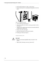
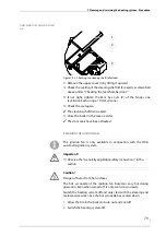
Remove the upper cover (1) by lifting it upward.

3.

Loosen the M10 union nut (SW 17) (3) and pull the flue gas
temperature sensor (2) out of the clamp screw connections.

4.

Clean the sensor surface with a moist cloth.

5.

Reinstall the flue gas temperature sensor (2) in the reverse
sequence.

6.

Close the boiler in the reverse order.

The flue gas temperature sensor has been cleaned.

C

LEANING


THE


PRIMARY


AIR


INLETS

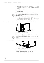
1.

Allow the fire in the boiler to burn out and cool off.

2.

Open the fuel chamber door.

See “Cleaning the fuel chamber” in “Cleaning the fuel chamber 
and ash compartment”
 in this section.

Important!

Observe the “Generally applicable safety instructions” in this 
section.

Figure 7/15 - Cleaning the flue gas temperature sensor

3

2

1

Important!

Observe the “Generally applicable safety instructions” in this 
section.

Summary of Contents for Euro 30

Page 1: ...hdg bavaria com HDG Euro 30 40 45 50 Operation Manual ...

Page 2: ......

Page 3: ... HDG Euro 30 40 45 50 14 Rear and side view of HDG Euro 30 40 45 50 15 3 2 Functional description 16 Boiler HDG Euro 30 40 45 50 16 Boiler and weather compensated heating control HDG Control 17 3 3 Technical data 18 3 4 Fuel quality requirements 19 Log wood 19 Wood chips 20 Pressed wood briquettes in accordance with DIN EN ISO 17225 3 21 Recommended fuel 21 Permitted fuel in accordance with 1st Fe...

Page 4: ...ing on the heating system 46 Requirements 46 Emergency heating switch 46 Fuel selection 47 6 3 Heating up the system 47 6 4 Performing a chimney sweep test 58 Before the test 58 On the day of the test 59 During the test 59 6 5 Switching off the heating system for repair work 61 6 6 Troubleshooting 62 7 Cleaning and servicing the heating system 63 7 1 Cleaning and servicing schedule 63 7 2 Procedur...

Page 5: ...l HDG Euro 30 40 45 50 Content 5 Inspecting the door seals for leaks 77 Cleaning the ignition fan 79 8 Notes on dismantling and disposal 81 8 1 Dismantling 81 8 2 Disposal 82 9 Declaration of Conformity 83 10 Index 84 ...

Page 6: ...correct at the time of going to press We reserve the right to make changes which may then differ from the technical details and illustrations in this Operating manual COPYRIGHT Written permission is required from HDG Bavaria GmbH for reprinting storage in a data processing system or transmission by electronic mechanical photographic or any other means and for copies or translations of this publica...

Page 7: ... This is a component that carries out a certain function in the heating system for example the thermal safety device TAS Central module Pre fabricated connection strip for electrical components Flue gas fan Creates a vacuum inside the boiler and provides the boiler with air for combustion HDG Control Boiler and heating system controller Lambda sensor Electrical component which monitors residual ox...

Page 8: ...of the device and understand the resulting risks Children may not play with the device Cleaning and user maintenance must not be carried out by children without supervision BASIC PRINCIPLES FOR THE CONTENT OF THE OPERATING MANUAL SCOPE The content of this operating manual is intended exclusively for the planning installation and operation of the HDG Euro 30 40 45 50 boiler The further implementati...

Page 9: ...s cooled down before touching non insulated components Danger Danger of asphyxiation due to carbon monoxide If the boiler is in operation carbon monoxide can be emitted through the open doors or lids Always keep the doors and lids closed Only open them when the boiler has finished burning Do not leave them open any longer than necessary and never leave them open unattended Warning Danger of fire W...

Page 10: ...ving parts When working on the flue gas fan disconnect it from the mains Danger Electric shock Working on live components such as the central module can result in an electric shock Work on the live components may only be carried out by a qualified electrician Make sure the system is disconnected from the mains and prevented from being switched on again Warning The boiler is under pressure Danger D...

Page 11: ...o lack of oxygen When working in areas marked with this symbol there is a danger of asphyxiation due to high concentrations of carbon monoxide Warning Automatic start up Working in areas marked with this symbol can lead to injuries due to automatic start up Danger Danger of explosion A concentration of carbon monoxide that is too high can result in an explosion Warning Danger from suspended loads ...

Page 12: ...r to beginning work particularly the chapter 2 Safety notes This is especially important for persons who only occasionally work on the heating system for example when cleaning or servicing it The Operating manual must always be kept readily accessible at the place where heating system is installed Instructions regarding disposal Additional information for the operator ...

Page 13: ...Control unit HDG Control Touch 2 Fuel chamber door 3 Fuel chamber door locking device 4 Actuator primary air 5 Ash door 6 Upright grate flap 7 Fly ash door 8 Actuator secondary air 9 Immersion sleeve cover cap for return temperature sensor Figure 3 1 Front view of HDG Euro 30 40 45 50 1 3 2 7 5 4 8 6 9 ...

Page 14: ...eflector plate 4 Heat exchanger surfaces 5 Secondary combustion chamber with chamber stones 6 Burner nozzle 7 Flue ash compartment 8 Ash compartment 9 Flat grate 10 Fuel chamber 11 Primary air inlets 12 Pneumatic with safety stop 13 Pneumatic spring Figure 3 2 Cross section of HDG Euro 30 40 45 50 13 8 6 5 4 3 2 1 11 10 12 7 9 ...

Page 15: ...door 11 Ignition fan only in connection with HDG automatic ignition 12 Differential pressure switch only in connection with HDG automatic ignition 13 Supply connection DN 32 inside thread 14 Immersion sleeve cover cap for flow return and STL sensors 15 Safety heat exchanger outlet DN 20 inside thread 16 Safety heat exchanger inlet DN 20 inside thread 17 Connection of immersion sleeve for thermal s...

Page 16: ...it This enables wood to be converted into heat energy in an environmentally sound and convenient manner COMBUSTION PROCESS Inside the HDG Euro 30 40 45 50 boiler fuel which has been manually placed in the fuel chamber 1 and ignited is degassed through the addition of primary air The resulting wood gas is mixed with secondary air in the combustion chamber 2 where it is burnt off Ashes are collected...

Page 17: ...tral module and control unit HDG Control Touch on the fuel chamber door of the boiler Using the control unit you can regulate the boiler and call up information on the current process HEATING CIRCUIT CONTROL The HDG Control controls the entire energy management of the heating system including the following depending on the version Accumulator management Weather compensated heating circuits Domesti...

Page 18: ...9 kg with scale liner Planning data for flue calculation DIN EN 13384 1 Flue gas temperature Tw at Nominal thermal power Minimum thermal power 140 C 140 C 160 C 140 C 170 C 140 C 180 C 140 C Flue gas mass flow at Nominal thermal power Minimum thermal power 0 0160 kg s 0 0160 kg s 0 0220 kg s 0 0160 kg s 0 0240 kg s 0 0160 kg s 0 0260 kg s 0 0160 kg s CO2content at nominal thermal power 16 4 16 7 1...

Page 19: ... contained in the wood the smaller the calorific value since the water vaporises in the course of the burning process and thereby consumes heat This leads to a decreased efficiency and thus to higher fuel consumption A higher water content in the fuel also Water side resistance at nominal thermal power 10 K 20 K 2400 Pa 640 Pa Other information Burning duration per filling with fuel in accordance ...

Page 20: ... of the fuel PARTICLE SIZE In accordance with DIN EN ISO 17225 4 the fuel specifications for wood chips are classified in P45S The numeric value of the P class refers to the size of the wood chips in mm which fit through a circular mesh with the indicated sieve opening size P45S For HDG Euro 30 40 45 50 wood chips classified in the P45S category or larger can be used as fuel WATER CONTENT The wate...

Page 21: ...E WITH DIN EN ISO 17225 3 Pressed wood briquettes are pressed shavings with or without various forms of additives with a diameter of more than 25 mm Essential criteria for the definition of the property classes are the length and diameter moisture content and ash content of the fuel LENGTH AND DIAMETER D100 L500 The diameter of the briquettes must not exceed 100 mm and the length must not exceed 5...

Page 22: ...og wood 5 shavings 5a wood briquettes and also fuel classes 6 and 7 may be used in the HDG Euro 30 40 45 50 heating system FUEL CLASS 6 Painted varnished or coated wood including remains thereof provided no wood protection agents have been applied or are present as the result of a treatment and coatings do not contain organic halogen compounds or contain heavy metals FUEL CLASS 7 Plywood chipboard...

Page 23: ...m C Return connection height 599 mm D Height at middle of the flue gas pipe connection 1106 mm E Boiler height 1374 mm F Height with open cleaning shaft lid 1920 mm G Height with open fuel chamber door 1941 mm H Height at edge of fuel chamber 1105 mm 1105 mm I Diameter of flue pipe connection 180 mm 180 mm J Flue gas fan overhang 216 mm K Boiler length 1256 mm L Length of boiler incl flue gas fan ...

Page 24: ...erative that the heating system is installed in accordance with the specifications of HDG Bavaria GmbH and that the minimum spacing requirements are observed Also note that the thresholds in DIN 4109 Soundproofing in building construction may not be exceeded More detailed information can be found in the relevant local and national regulations We recommend that objects which are not needed for the ...

Page 25: ...imensions of the boiler and ensure the minimum clearances Figure 4 2 Required room sizes and minimum clearances F D E C B A G HDG Euro 30 40 45 50 A at least 750 mm B at least 200 or 800 mm C at least 800 or 200 mm D 1610 mm E at least 2600 mm F at least 1800 mm G at least 800 mm Minimum ceiling height 2000 mm Recommended room height 2300 mm Installation dimensions 1380 x 800 x 1610 mm Table 4 2 R...

Page 26: ...de air leaking in Air penetrating from the outside speeds up the cooling of the flue gases These requirements correspond to chimneys of the type conforming to DIN EN 13384 1 2003 03 Thermal and fluid dynamic calculation methods Free standing chimneys require particularly good insulation CHIMNEY DIMENSIONS The system may only be connected to a chimney which has been dimensioned in accordance with D...

Page 27: ...onstructional reasons these must be longer than 1 m they should be adequately insulated at least 5 cm of mineral wool or equivalent material and if possible fitted with an upward inclination The following should also be considered The connecting piece may not protrude into the chimney If the system flue gas pipe has a larger diameter than the chimney the connecting piece must reduce its diameter t...

Page 28: ... heating load the lowest outside temperature of the relevant climate zone e g 15 C is used These conditions only apply a few days per year thus the thermal performance of the heating system is greater than required on most days when heating is needed As the boiler for this system is rated for a nominal load the use of an accumulator is required The size of the accumulator must be adapted to the bo...

Page 29: ...is listed in chapter 3 Mode of operation section 3 3 Technical data The control of the return temperature is handled by the HDG Control control unit The return temperature control consists of a 3 way mixing valve with a 230 V servo drive running time 120 240 s and a circulation pump from energy efficiency class A For the HDG Euro 30 40 50 we recommend Wilo 30 1 7 5 3 way mixing valve DN 32 or equi...

Page 30: ...alist heating company and an electrician The hydraulic connection depends on the schematic diagram selected in the respective HDG Control system Danger Risk of material damage and injury due to incorrect installation Installing the system requires comprehensive specialist knowledge If installed by untrained persons the heating system can be damaged and persons may be injured due to secondary damag...

Page 31: ...ection 4 2 Structural requirements under Required room sizes and minimum clearances 6 Align the boiler 2 with plastic plates or flat steel strips not included in the scope of delivery so that it is horizontal 7 Remove the eyebolt 1 8 Place the cover cap on the control console The HDG Euro 30 40 45 50 boiler has been placed in position Warning Danger from suspended loads The boiler weighs over 950 ...

Page 32: ...d for them 5 Secure the square shafts with the M12 screws SW19 2 6 Place the respective spacer plates 5 under the installation aid 7 Turn each of the M16 spindles 4 SW24 until the boiler is completely supported on the installation aid 8 Remove the pallet 1 Important When using the installation aid observe the required minimum clearance of 60 cm to the side walls in order to be able to later remove...

Page 33: ... REMOVING TRANSPORT SAFETY DEVICE 1 Remove the upper cover 1 by lifting it upward 2 Open the cleaning shaft lid 2 Warning Danger of injury If you screw a spindle on a corner down completely there is the risk that the boiler will tip over This could cause serious injuries as well as damage to the boiler Turn each of the spindles in alternating brief turns Figure 4 7 Using the installation aid 1 The...

Page 34: ...0 45 50 Caution Danger of injury The cleaning shaft lid is heavy and may fall shut This could injure hands and fingers Take care each time you open or close the cleaning shaft lid that it does not unexpectedly fall shut The inner transport safety device 1 can be disposed of with the rest of the waste The cable set for the HDG Control control unit is already connected on the central module at the t...

Page 35: ...al plans HDG Euro 30 40 45 50 Figure 4 11 Installing the control unit 2 1 3 The flow return and STL sensors are already installed upon delivery Depending on the hydraulic application an EM4 expansion module may have to be used Important If the EM4 expansion module is used this must be installed on the rear above the central module If expansion module EM8 or EM8 4 is used alternatively or in additi...

Page 36: ...NG THE HDG AUTOMATIC IGNITION Caution Malfunctions due to incorrect cabling If live cables and sensor cables are installed in the same ducts it can cause the sensors to malfunction Ensure that the live wires and the sensor cables are installed in different cable ducts Please note that here only the assembly of the HDG Control unit is described The remaining electrical installations depend on the h...

Page 37: ...n the differential pressure switch 2 8 Place the adjusting ring 3 on the ignition pipe 6 9 Push the ignition fan 8 into the ignition pipe 6 10 Using the M8 hexagon socket screw SW4 on the adjusting ring 3 secure the ignition fan 8 in the ignition pipe 6 11 Insert the flat plug receptacle of the brown wire from the cable for the differential pressure switch 2 into socket 1 11 2 Dismantle the dummy ...

Page 38: ...ly fireproof silicone or with a suitable mortar The boiler is now connected to the chimney 4 8 Electrical system The electrical connections must be made in accordance with DIN IEC 60364 Setting up low voltage electrical installations The technical details are described in chapter 3 Mode of operation section 3 3 Technical data The electrical diagram and the hydraulic plan are enclosed with the docu...

Page 39: ...er the safety heat exchanger and thermal safety device can only serve their purpose if the following requirements have been met A flow pressure of at least two bar must be available at the cold water inlet of the safety heat exchanger The distance between the supply and return lines of the thermal safety device and the safety heat exchanger should not be less than their nominal width The supply li...

Page 40: ...nnection bushing for TAS immersion sleeve DN 15 inside thread 2 Safety heat exchanger inlet DN 20 inside thread 3 Safety heat exchanger outlet DN 20 inside thread 4 Thermal safety device TAS 5 Runoff connection to drainage system Figure 4 16 Thermal safety device 3 2 1 4 5 ...

Page 41: ...essel has been adapted to on site conditions All required DIN EN 12828 safety devices have been installed and are ready for operation The power supply to all components is ensured Makeshift solutions are not sufficient The chimney installation corresponds to the legal regulations All doors and openings on the boiler and on the chimney connection pipe have been checked for a proper seal Air supply ...

Page 42: ...AIR GUIDE AND THE GRATE HEIGHT FOR THE RESPECTIVE FUEL An optimum gasifying of the fuel and thus an efficient combustion can only be achieved if the boiler is preset for the fuel to be used and its burning properties Adapting to the on site conditions is also of critical importance Important For safety reasons the system component test may only be conducted when there is no fuel in the boiler and ...

Page 43: ... air adjuster plate threshold of upper ash door 7 mm 10 15 mm Air damper on upright grate flap closed above open halfway below closed above open halfway below Flat grate bottom raised 55 mm Table 5 1 Setting of the primary air guide and grate height The above settings are suitable for operating the HDG Euro 30 40 45 50 boiler for materials with technical burning characteristics in accordance with ...

Page 44: ...te lifter can be changed in order to correct the gas quantity during degassing and thus avoid pulsating sudden igniting due to lack of oxygen or insufficient flue gas temperatures This is required in the case of larger deviations from the recommended fuel or deviations from the required temperatures in order to ensure safe operation of the log wood boiler Figure 5 2 Adjusting the air damper 1 2 3 ...

Page 45: ...ose the boiler in the reverse order The grate lifting bar is now set Figure 5 3 Grate lifter 1 2 4 3 The three flat grate elements are of differing width Make sure that the flat grate elements are put back in the correct manner and order Caution Danger of injury The flat grate elements are heavy Hands and fingers could be crushed during their removal installation Exercise caution so that your hand...

Page 46: ...ed to the mains supply through an emergency heating switch provided by the customer or through a circuit breaker in the mains distribution box of the building 1 Switch on the heating system at the corresponding circuit breaker or the emergency heating switch provided by the customer The heating system is now under voltage The control is activated The heating system is switched on and ready for ope...

Page 47: ... occur in the combustion and in the operation of the heating system If necessary the settings of the heating system must be adjusted for the changed fuel Caution Hot surfaces Contact with the hot surfaces of the boiler can lead to burns Wait until the boiler has cooled down before touching non insulated components Warning Danger of asphyxiation due to carbon monoxide If the boiler is operating car...

Page 48: ... Danger of injury The fuel chamber door is heavy and may fall shut This could injure hands and fingers Take care each time you open or close the fuel chamber door that it does not unexpectedly fall shut We recommend wearing leather gloves when heating up the system Caution Damage caused by unintended fuel fomentation Residual embers in the fuel chamber can lead to unintended fuel fomentation This ...

Page 49: ...tings with point 17 CHANGING THE SETTINGS 4 If you wish to change the settings press the appropriate setting 5 Press the Wood type The Wood type selection window appears in the display 6 Select the type of wood used 7 Confirm your input by pressing the Confirm button 1 The Fill up Reload window appears in the display again 8 Press Wood moisture The Wood moisture selection window appears in the dis...

Page 50: ...on of Automatic ignition mode the Automatic ignition selection window 14 Select the type of automatic ignition 15 Confirm your input by pressing the Confirm button 1 Figure 6 4 Query wood moisture 1 Ignition modes Manual The fuel is ignited manually with firelighters Electrical The fuel is automatically ignited by the ignition fan directly after filling regardless of the accumulator temperature we...

Page 51: ...e time is reached at the same time in accordance with the set weekly programme Accumulator temperature and requirement The automatic ignition starts after the set accumulator temperature is undershot and if there is a requirement from a consumer heating circuits domestic hot water at the same time Accumulator temperature requirement and weekly programme The automatic ignition starts after the set ...

Page 52: ...ion message appears in the display 18 Press the lock 1 of the fuel chamber door downward 19 Wait until the progress bar is full The Openfuelchamberdoorslowly message appears in the display Figure 6 8 Do not open the fuel chamber door Figure 6 9 Opening the fuel chamber door to the safety position Figure 6 10 Unlocking the fuel chamber door 1 Figure 6 11 Open the fuel chamber door slowly ...

Page 53: ...hly flammable material small dry pieces of wood paper cardboard in front of the burner nozzle 2 on the grate 3 and stack it 15 to 20 cm high 24 Ignite the fuel 25 Allow the fuel to generate a good fire Figure 6 12 Opening the fuel chamber door 2 1 Figure 6 13 Removing ash 3 2 1 For kindling we recommend log wood with a diameter of D5 2 5 cm We recommend using bio firelighters consisting of wood sh...

Page 54: ...the back The fuel chamber door can now be closed 28 Close the fuel chamber door 1 The Clean reload ignite message appears in the display 29 Confirm your input by pressing the Confirm 1 button The Ignite message appears in the display Figure 6 14 Closing the fuel chamber door 1 2 Figure 6 15 Cleaning reloading igniting 1 Figure 6 16 Ignition ...

Page 55: ...s of dry wood in front of the igniter gun and approx 15 20 cm high on the burner nozzle on the grate 17 Lay some small pieces of cardboard in front of the igniter gun on the wood inside the fuel chamber 18 Fill up the fuel chamber with fuel 19 Close the fuel chamber door The Clean reload ignite message appears in the display Figure 6 17 Opening the ash door 1 Figure 6 18 Closing the doors Only put...

Page 56: ...l the progress bar is full The Underpressure test message appears in the display 23 Wait until the progress bar is full The ignition fan starts The Ignite message appears in the display The HDG Euro 30 40 45 50 boiler is now heated up Figure 6 20 Closing the doors Figure 6 21 Underpressure test The differential pressure switch enables the ignition fan if the preset underpressure is reached Figure ...

Page 57: ...chamber according to the percentage specified on the display 19 Close the fuel chamber door The Clean reload ignite message appears in the display 20 Confirm your input by pressing the Confirm 1 button The Close doors message appears in the display 21 Make sure that all of the doors are closed 22 Wait until the progress bar is full The Ready for ignition message appears in the display Only put in ...

Page 58: ...ing To ensure a stable operating ability sufficient heat transfer must occur while operating at full load TEST EVERY TWO YEARS In Germany regular inspections every two years must be carried out in accordance with the requirements of the federal emission limits 1 BImSchV BEFORE THE TEST 1 Clean the boiler completely about three to four days before the chimney sweep test See section 7 1 Cleaning and...

Page 59: ...eriod between the cleaning and the chimney sweep test Oakwood wood briquettes boards scrap wood and wood chips are not suitable for the chimney sweep test At the start of the test the boiler temperature should not be below 60 C The temperature of the accumulator should not be higher than 60 C Ensure that the heating circuit has sufficient heat transfer capacity The heating system must be fitted wi...

Page 60: ... to the main menu 8 Press the Messages Maintenance field The display switches to the Messages Maintenance area 9 Press the Chimney sweep test field The display switches to Chimney sweep test 10 Press Test in nominal load 1 to carry out the chimney sweep test in nominal load operation A security query appears 11 Press Yes 1 The display switches to the chimney sweep test Important The bed of embers ...

Page 61: ...2 Switch the heating system off See the HDG Control operating manual chapter 5 Using the control unit section 5 3 Switching off the heating system 3 Switch off the emergency heating switch if installed or the corresponding mains electricity circuit breaker The heating system is switched off and without current Figure 6 28 Chimney sweep test 1 Pressing the Cancel test button 1 cancels the chimney s...

Page 62: ...the heating system Troubleshooting 62 6 6 Troubleshooting If a fault occurs in the heating system this is shown in the display of the HDG Control See the HDG Control operating manual chapter 10 Troubleshooting ...

Page 63: ...st heating company The specified cleaning intervals are guidelines These intervals may vary according to the quality of the fuel and the power used by the heating system Interval Component See page Weekly as required Clean fuel chamber and ash compartment Inspect pneumatic springs 65 68 Monthly during the heating period approx 240 operating hours Clean heat exchanger surfaces and combustion chambe...

Page 64: ...g system off and only start with the cleaning and maintenance work when the surfaces have cooled down Warning Danger of fire When the heating system is in operation open doors and lids constitute a fire hazard Always keep the doors and lids closed Only open them when the boiler has finished burning Do not leave them open any longer than necessary and never leave them open unattended Warning Danger...

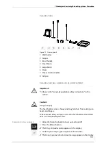
Page 65: ... Press the Reload button The Fill up Reload window appears in the display 3 Confirm your entry by pressing the Confirm button TheDonotopenfuelchamberdoormessage appears in thedisplay Figure 7 1 Cleaning tools 1 3 4 5 6 7 2 8 Important Observe the Generally applicable safety instructions in this section Caution Danger of injury The fuel chamber door is heavy and may fall shut This could injure hand...

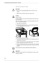
Page 66: ...ears in the display 7 Lift the lock 2 of the fuel chamber door and open the door 1 slowly until it is horizontal The fuel chamber door opens automatically The catch on the right pneumatic spring latches in place 8 Open the ash door 1 9 Open the upright grate flap 2 10 Check the fuel chamber 4 for ash and any other dirt and if necessary remove this from the grate 3 using the supplied cleaning tools...

Page 67: ...e combustion residue into the ash pan 2 18 Empty the combustion residue into a fireproof container 19 Close the boiler in the reverse order 20 The Clean reload ignite message appears in the display 21 Press the Confirm button 22 Press the Reload button The Fill Reload message appears in the display 23 Press the Cancel button The security query Do you really want to switch off the boiler appears in...

Page 68: ... springs 3 are in order If the fuel chamber door does not open from the horizontal position or has to be lifted the pneumatic springs 3 must be replaced Important Observe the Generally applicable safety instructions in this section Caution Danger of injury The fuel chamber door is heavy and may fall shut This could injure hands and fingers Take care each time you open or close the fuel chamber doo...

Page 69: ...the limit stop the spring must be replaced 5 Close the boiler in the reverse order The pneumatic spring inspection is completed CLEANING THE HEAT EXCHANGER SURFACES AND COMBUSTION CHAMBER 1 Allow the fire in the boiler to burn out and cool off Figure 7 7 Inspecting the fuel chamber door catch 1 2 Have the spring replaced on the catch of the fuel chamber door by authorised and qualified specialists...

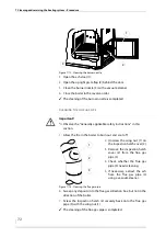
Page 70: ... star grip screws on left and right hand sides of the boiler and remove one of the flue ash doors 1 4 Pull out the flue gas deflector plate 1 in an upward direction Figure 7 9 Removing the flue gas deflector plate 1 Important When cleaning the heat exchanger surfaces always first push the cleaning brush all the way down and through before you pull it up again so that the wire bristles of the brush...

Page 71: ...sh into a fireproof container 13 Close the boiler in the reverse order The cleaning of the heat exchanger surfaces and combustion chamber is completed CLEANING THE BURNER NOZZLE 1 Allow the fire in the boiler to burn out and cool off 2 Open the fuel chamber door See Cleaning the fuel chamber in Cleaning the fuel chamber and ash compartment in this section Figure 7 11 Removing the flue ash 1 2 Impo...

Page 72: ...box but not in the direction of the boiler 7 Screw the inspection hatch 2 securely back onto the flue gas pipe 3 with the wing nut 1 The cleaning of the flue gas pipe is completed Figure 7 12 Cleaning the burner nozzle 3 2 1 Important Observe the Generally applicable safety instructions in this section 2 Unscrew the wing nut 1 on the inspection hatch cover 2 3 Remove the inspection hatch cover 2 f...

Page 73: ...6 Reinstall the lambda sensor 2 in the reverse sequence 7 Check the lambda sensor 2 for a secure fit 8 Carefully tighten the lambda sensor 2 with a 22 mm spanner The cleaning of the lambda sensor is completed Important Observe the Generally applicable safety instructions in this section Figure 7 14 Cleaning the lambda sensor 1 3 4 2 Important Steel bristles will damage the lambda sensor Important ...

Page 74: ...the flue gas temperature sensor 2 in the reverse sequence 6 Close the boiler in the reverse order The flue gas temperature sensor has been cleaned CLEANING THE PRIMARY AIR INLETS 1 Allow the fire in the boiler to burn out and cool off 2 Open the fuel chamber door See Cleaning the fuel chamber in Cleaning the fuel chamber and ash compartment in this section Important Observe the Generally applicabl...

Page 75: ...ompleted CLEANING THE FLUE GAS FAN 1 Allow the fire in the boiler to burn out and cool off 2 Disconnect the plug 2 from the flue gas fan 1 Figure 7 16 Cleaning the primary air inlets 1 Important Observe the Generally applicable safety instructions in this section Caution Risk of injury from automatically driven components Working on the flue gas fan can lead to hand injuries due to the moving part...

Page 76: ... gap behind it with a cleaning tool 7 Inspect the seal and the contact surfaces 2 around the flue fan and the flue gas collection box 8 Replace the seal if it is damaged 9 Reinstall the flue gas fan in the reverse sequence The flue gas fan has been cleaned CLEAN AIR CONTROL UNIT 1 Allow the fire in the boiler to burn out and cool off Figure 7 18 Cleaning the flue gas fan 1 3 2 Important Observe th...

Page 77: ...hese are movable 5 Close the air control unit in reverse order The air control unit is cleaned INSPECTING THE DOOR SEALS FOR LEAKS CHECKING THE FUEL CHAMBER DOOR 1 Allow the fire in the boiler to burn out and cool off 2 Open the fuel chamber door See Cleaning the fuel chamber in Cleaning the fuel chamber and ash compartment in this section Figure 7 19 Cleaning the air control unit 2 1 3 Important ...

Page 78: ... all four of the contact surfaces 2 7 Remove the paper and close the fuel chamber door 1 CHECKING THE ASH DOOR 8 Check the sealing of the ash door 1 exactly as described above under Checking the fuel chamber door CHECKING THE FLY ASH DOOR 9 Make sure that both fly ash doors 2 have a tight seal 10 Tighten the two star grip screws 1 if necessary If a correction to the fuel chamber door is necessary ...

Page 79: ...oor seals have been checked CLEANING THE IGNITION FAN 1 Allow the fire in the boiler to burn out and cool off 2 Switch the heating system off Figure 7 23 Checking the cleaning shaft lid for leaks 1 2 3 The ignition fan is only available in connection with the HDG automatic ignition system Important Observe the Generally applicable safety instructions in this section Caution Danger of burns from ho...

Page 80: ...ir nozzle 5 8 Remove the insulating tube 6 and the seal 3 9 Pull the heating element 2 out of the plug contacts 7 10 Check the heating element 2 for dirt 11 Remove any dirt by blowing it off 12 Check the photocell 1 for dirt 13 Remove any dirt using a cotton swab 14 Reinstall the ignition fan into the heating system in the reverse sequence 15 Re starting the heating system See the HDG Control oper...

Page 81: ...r supply 4 Once it has cooled down drain the heating water from the system 5 Observe the safety regulations for personnel when disconnecting the boiler from the heating system 6 Dismantle the individual components of the boiler The boiler has been dismantled Danger Material damage and personal injury due to incorrect dismantling Dismantling the system requires comprehensive specialist knowledge If...

Page 82: ...al recycling centre Central heating boiler Cladding The electrical components can also be recycled via a local recycling centre Fibreglass mineral wool and plastic parts should be brought to the relevant waste disposal centres Oily or greasy components and condensers may only be disposed of through a specialist waste disposal centre ...

Page 83: ...an Parliament and of the Council of 15 December 2004 on the approximation of the laws of the Member States relating to electromagnetic compatibility and repealing Directive 89 336 EEC 97 23 EC Pressure Equipment Directive 97 23 EC on the approximation of the laws of the Member States concerning pressure equipment In accordance with section 2 of article 7 the applied harmonized regulations are to b...

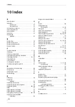
Page 84: ...l system 28 38 EM4 15 EM4 expansion module 15 EM8 expansion module 35 Emergency heating switch 42 46 Expansion module EM4 Installing 35 Expansion module EM8 4 35 F Faults 62 Filling draining connection 15 18 Flat grate 14 Flue ash compartment 14 Flue calculation 18 26 Flue draught requirement 18 26 59 Flue gas deflector plate 14 Flue gas fan 7 15 Flue gas mass flow 18 Flue gas pipe connection 15 1...

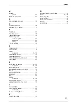
Page 85: ... sensor 13 Return temperature 29 Return temperature minimum 18 Room height 25 S Safety heat exchanger 14 39 connection 15 18 Scope of delivery 30 Secondary combustion chamber 14 Sensor 7 Sound pressure level 19 Spare parts 63 STL 15 Supply connection 15 18 Supply temp sensor 15 Supply temperature maximum 18 T Technical data 18 Thermal safety device 7 39 connection 15 Transport safety device 33 U U...

Page 86: ...10 Index 86 HDG Euro 30 40 45 50 Version 1 de HDG Bavaria GmbH 06 2008 ...

Page 87: ......

Page 88: ...aria GmbH Heizsysteme für Holz Siemensstraße 22 D 84323 Massing Tel 49 0 8724 897 0 info hdg bavaria com www hdg bavaria com Art Nr 9980001630 V 05 en 03 2015 Translation of the original operating instructions ...

Reviews: