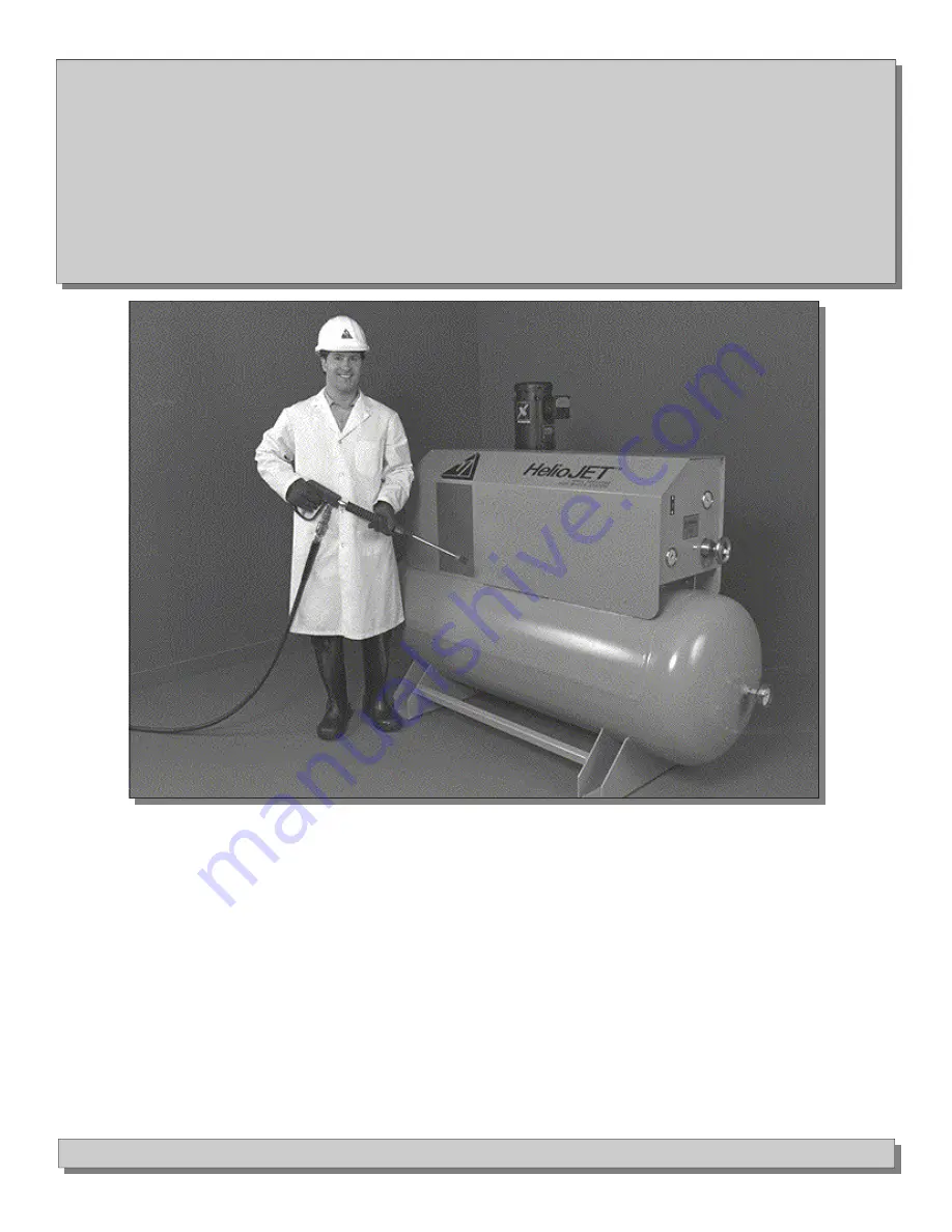
HelioJET™ Model Central
Cleaning
C-100
HelioJET Cleaning Technologies
• 57 North Street / Suite 120 LeRoy, NY 14482 • Tel 585-768-8710 Fax 585-768-9209
Installation
Operation
Maintenance
M-C100-02-01
Page 1: ...HelioJET Model Central Cleaning C 100 HelioJET Cleaning Technologies 57 North Street Suite 120 LeRoy NY 14482 Tel 585 768 8710 Fax 585 768 9209 Installation Operation Maintenance M C100 02 01 ...
Page 2: ...of Contents Important Safety Precautions 3 How it Works 4 5 Installation 6 10 Start up 11 13 Trouble Shooting 14 15 Preventative Maintenance 16 19 Major Components and Spare Parts 20 22 Limited Warranty 23 2 ...
Page 3: ...ose 3 ALWAYS allow hose a minimum 9 inch bend radius 4 ALWAYS check hose for kinks or abrasions that may develop into a rupture 5 ALWAYS use hardware valves fittings quick disconnects etc which are rated for the maximum discharge pressure at which you could be operating REMEMBER The HelioPAC is a powerful fluid pressure amplifier and condenser which can multiply the inlet pressure several times Fo...
Page 4: ...e This transfer causes a significant increase in the temperature and velocity of the incoming water The HelioPAC converts this velocity to pressure increasing the pressure of the incoming water up to 10 times 4 Liquid Vapor Secondary Inlet Optional Start up Overflow Discharge High Velocity Stream Water Supply Steam Supply Start up Overflow to Drain High Velocity Hot Water Supersonic Steam Flow Vel...
Page 5: ...3 and the stabilizer pump 4 which sends cold water through the water inlet line to supply the HelioPAC 7 The flowing water closes the flow switch circuit 5 which energizes the air actuated steam valve 6 allowing steam to flow to the HelioPAC where it encounters the incoming water The HelioPAC starts and fills the reserve tank to the desired pressure as set by the pressure switch When the pre set p...
Page 6: ...oblem be sure that the HelioJET is supplied with soft water This will prevent fouling in the system Note To optimize performance always avoid pressure drops in supply lines Locate the HelioJET as close as possible to the water and steam source and never undersize piping If the HelioJET must be located a considerable distance from supply mains increase pipe diameters feeding the unit Avoid the use ...
Page 7: ...acuum Gauge 3 Discharge Line to Plant 2 NPT 10 Thermometer 4 Start up Overflow to Drain 1 1 2 NPT 11 Handwheel Adjustment 5 Electrical Control Box 12 Power Switch 6 Steam Trap 1 2 NPT 13 High Low Pressure Switch 7 Pressure Reserve Tank 300 Gallon A S M E rated 600 psi MWP Figure 3 62 74 7 5 13 1 4 2 12 9 HelioPAC 11 8 3 10 7 6 52 80 ...
Page 8: ...g and components such as starter overload etc are included in the package High Pressure Discharge Piping To supply pressurized hot water to spray gun stations or other cleaning equipment in your facility connect high pressure piping to the discharge ball valve 2 located at the rear of the pressure reserve tank pg 7 item 3 Use at least 2 discharge pipe for the riser and main feeding the plant Do no...
Page 9: ... Alarm Light Condensate Indicator 8 6 2 4 7 1 3 5 High Probe Reference Probe Ground Tank if metallic may be used instead of reference probe Solid State Relay Module 9 10 11 Steam Probe Relay Motor Starter Overload 5 1 1 1 1 2 6 1A 1A 9 Push to Test 2B 1 9 Electrical Schematic C 100 Central System 460V 3 Phase D00306 Pressure Switch 3 4 Discharge Solenoid Air Solenoid Vacuum Switch 7 8 9 9 3 9 Disc...
Page 10: ...8 Air Supply Valve 9 Foaming Nozzle 10 G 7 Spray Gun up to 8 GPM 11 1 2 Hose Swivel 12 3 4 Quick Disconnect Fem 13 3 4 Quick Disconect Male 14 3 4 Foam Hose 15 1 2 Spray Hose 16 3 4 X 1 2 Bushing 17 Detergent Pick up Tube Note Items 12 and 13 are optional and serve to make the spray gun and hose mobile 17 16 14 15 G 7 Spray Gun Typical Hot Foam Sanitize Installation and Rinse Station 10 Figure 4 3...
Page 11: ...ake adjustments Initial Calibration and Start up Before attempting to start this system be sure it has been installed in accordance with all previous instructions and that the proper procedures have been followed If you have any questions contact the HelioJET Technical Service Department at 1 800 444 3546 Please read all of the following steps before beginning and be sure to follow them in proper ...
Page 12: ...iping installation Depending on the lengths of piping involved 30 seconds to 1 minuet of flush time is usually adequate Caution Be careful you are dealing with extremely hot water that can easily burn the skin Stand clear and open valve slowly Step 12 After flushing lines close discharge valves at the drops and shut HelioJET System down simply turn off power switch in order to install spray equipm...
Page 13: ...ter Tank Air Charge Valve Steam In To Spray Stations 2 Discharge Ball Valve System On Off Switch Start Up Overflow Initial Calibration Start up High low Pressure Switch Figure 5 High Setting upper dial Low Setting lower dial C 100 System Figure 6 Power Switch Discharge Pressure Gauge Discharge Thermometer Start Up Vacuum Gauge Set at 8 vacuum Start Up Overflow Drain Air Actuated Steam Valve Steam ...
Page 14: ... opening of the air actuated steam valve If the flow switch does not function properly it may prevent the opening of the steam valve Refer to page 16 Flow Switch Maintenance in the Preventative Maintenance section of this manual Problem I turned the power switch off while the system was in the midst of a cycle building pressure in the reserve tank When I turned it on again it started to overflow a...
Page 15: ...ernal condition of the overflow check valve If check valve seat is lodged or damaged it can obstruct the overflow line This may prevent start up disturb the vacuum reading or cause the unit to continuously overflow water and or steam vapor See page 21 item 12 F Is steam pressure at least 75 psi Perhaps it is at the boiler but there are line losses making it less at the HelioJET In most cases Helio...
Page 16: ...for the air actuated steam valve When water supply to the HelioJET is adequate the flowing water lifts the metering disc which raises the magnet The magnet completes the circuit allowing power to the steam valve If the flow switch does not function properly it will affect steam valve operation Inspect the magnet and other components to be sure they are intact Body Housing Bonnet Assembly Flow Swit...
Page 17: ...solenoid Does air continuously leak from the solenoid even when the system is not running If so replace the solenoid Air Actuated Steam Valve 1 2 3 4 Valve Body Actuator Head Assembly Steam out Steam in Steam Valve Part Components Number Complete Valve Assembly S AVP 2 05 Actuator Head Assembly ACT 13 Pilot Assembly S PV 01 1 Conduit Plug CP 01 2 Solenoid SOL 01 3 Adapter ADA 01 4 Valve Seat 17 RK...
Page 18: ...si If it is less you may have lost some of the charge If no air discharges from the gun at all the air cushion has been depleted and it must be replenished B Excessive noise can also be caused by a faulty overflow check valve If the overflow check valve does not seat properly it can actually cause excessive air intake through the start up overflow line This can result in increased noise level If t...
Page 19: ... a result of low vacuum is usually accompanied by an increase in noise B Plugged Air Intake The air nozzle and air check valve must be clean and open in order for the HelioJET to properly draw in air from the atmosphere To check whether or not the air intake is clean and open for free air flow be sure the start up vacuum gauge reads a 8 vacuum when the system is running While the HelioJET is runni...
Page 20: ...632092 31 Ball Valve BV 1 2 02 32 Nipple 616107 33 Check Valve CV 1 2 05 34 Nipple 616107 35 Bushing 625035 Start up overflow Assembly complete 36 Nozzle 100054 0025 37 Check Valve CV 1 4 03 38 Nipple 616054 39 Nipple 616227 40 Vacuum Gauge 620030 41 Check Valve CV 1 1 2 05 42 Pig Tail 630004 43 Coupling 622004 44 Snubber 620032 PAC 100 Major Components After a long period of operation wear will b...
Page 21: ...HelioJET Major Components C 100 17 1 5 4 3 2 16 15 14 7 6 11 10 9 8 13 12 25 23 22 24 21 20 19 18 26 29 28 27 ...
Page 22: ...am Strainer 2 1 2 621012 2 1 2 14 Steam Trap 637014 15 Condensate Steam Probe Not Shown 629228 16 Air Nozzle 100054 0020 17 Discharge Hose 632094 035 18 Tank Check Valve CV 1 1 2 04 19 Air Actuated Discharge Valve tank AVB 1 1 2 05 20 Tank Air Charge Valve BV 1 4 01 21 Safety Relief Valve RV 600 02 22 Air Actuated Discharge Valve plant AVB 2 07 23 Quick Disconnect Coupler Air Supply 631002 24 Quic...
Page 23: ...ructions To obtain service under this warranty the defective product must be returned to HCT s factory in LeRoy New York together with proof of purchase failure date and supporting installation data Any defective products to be returned to the factory must be sent freight prepaid documentation to support the warranty claim and or a Return Material Authorization must be included if so instructed HE...
Page 24: ...57 North Street Suite 120 LeRoy NY 14482 Tel 585 768 8710 ...