Heater System Solving Guide
FAULT CODE THUMBNAILS –
PAGE
F 1
FAUL
T CODE THUMBNAILS –
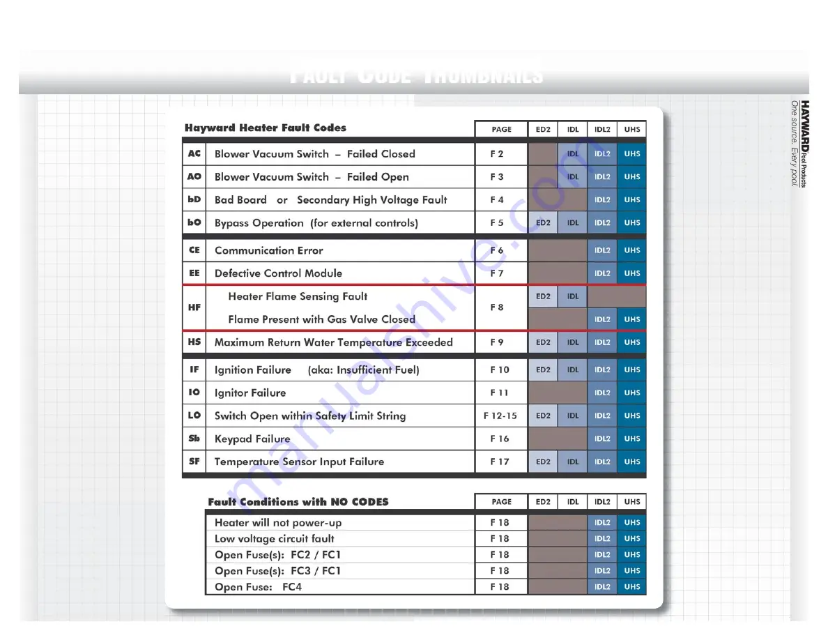
Fault Code Thumbnails
F
AULT
C
ODE
T
HUMBNAILS
Page 1: ...Heater System Solving Guide FAULT CODE THUMBNAILS PAGE F 1 FAULT CODE THUMBNAILS PAGE F 1 Fault Code Thumbnails FAULT CODE THUMBNAILS ...
Page 2: ...start up the control module will not start the blower Pre check is executed by the control module PARTS THAT MAY BE NEEDED Blower Vacuum Switch Control Module DIAGNOSTIC SEQUENCE A Disconnect the blower plug from the control module With the heater off measure the control module receptacle s continuity across pins 1 and 2 UHS IDL2 IDL and pins 3 4 IDL2 IDL only If either is closed replace the contr...
Page 3: ...st be securely fastened to spade terminals on vacuum switch C Check for faulty blower wiring or connection Plug on blower must be securely fastened to control module D Check for defective vacuum switch by disconnecting blower plug from control module Measure resistance across blower windings Winding resistance across lead should be in the following range IDL Black to White 30 45 ohms Red to White ...
Page 4: ...en FC4 Fuse B Verify high voltage output from fuse board Disconnect plug from P6 connector of fuse board Measure for 120VAC across pins 3 and 5 of P6 receptacle on fuse board If OK reconnect plug and proceed to step 3 If not OK go to step 4 C Check for defective wiring harness Disconnect plug from E10 connector of contol module Measure for 120VAC across pins 1 and 3 of plug on wiring harness If OK...
Page 5: ...N FOR EXTERNAL CONTROLS UHS IDL2 IDL ED2 The bo code is more of an information code than a fault code with the bo standing for Bypass Operation A bo code indicates the heater s internal thermistor is disabled allowing the external thermostat control to operate This prevents any confusion between the two temperature sensing devices during heater operation though the heater s thermistor will still p...
Page 6: ...on board and the display board is not established within 3 seconds of power up an error will be displayed After communication is established if it is lost for 30 seconds the er ror will be displayed The error code will be cleared upon a valid data exchange between boards DIAGNOSTIC SEQUENCE A Power down heater and re power This is similar to rebooting a com puter B If rebooting does not solve the ...
Page 7: ... 7 Heater System Solving Guide Fault Code Thumbnails EE Electrical Error FAULT CODE THUMBNAILS EE ELECTRICAL ERROR EE ELECTRICAL ERROR PARTS THAT MAY BE NEEDED Control Module Ignition Board DIAGNOSTIC SEQUENCE Replace the Control Module Ignition Board UHS IDL2 ...
Page 8: ...dule Ignition Board DIAGNOSTIC SEQUENCE A Check all wiring and connections for Flame sensor B Replace flame sensor IDL or ignitor ED2 C Replace control module ignition board if problem still exists HF FLAME PRESENT WITH GAS VALVE CLOSED UHS IDL2 PARTS THAT MAY BE NEEDED Gas Valve If flame is sensed without the gas valve energized the control will go into lockout DIAGNOSTIC SEQUENCE SHUT OFF GAS TO...
Page 9: ... MAY BE NEEDED Control Module External Thermostat if system uses one NOTE In most cases no replacement part will be needed DIAGNOSTIC SEQUENCE A Verify water flow is adequate Low water flow will cause high temperature Generally 25 gpm is needed by smaller heaters while 300 000 btu h heaters may require 40 gpm or more See heater s operating manual B Verify set point setting of remote thermostat us ...
Page 10: ...s train is correct The source of an IF code is found in the gas train 90 of the time DIAGNOSTIC SEQUENCE A Ensure that main gas shutoff adjacent to heater is open Ensure that knob on gas valve inside unit is in on position If OK proceed to next step B Check for low gas supply pressure by ensuring inlet gas supply pres sure is between the minimum and maximum values indicated on rating plate If OK p...
Page 11: ...Failure FAULT CODE THUMBNAILS IO IGNITOR FAILURE IO IGNITOR FAILURE PARTS THAT MAY BE NEEDED Ignitor Control Module Ignition Board DIAGNOSTIC SEQUENCE A Check for faulty wiring or connection B Replace ignitor C Replace Control Module Ignition Board NOTE Red letters above correspond with adjacent illustrations IDL2 UHS B C B C ...
Page 12: ...ILS PAGE F 12 Heater System Solving Guide Fault Code Thumbnails LO Switch Open within Safety Limit String UHS SEE PAGE F13 IDL2 SEE PAGE F13 IDL SEE PAGE F14 ED2 SEE PAGE F15 FAULT CODE THUMBNAILS LO SWITCH OPEN WITHIN SAFETY LIMIT STRING LO SWITCH OPEN WITHIN SAFETY LIMIT STRING ...
Page 13: ...LO does not clear the water pressure switch is defective and must be replaced DIAGNOSTIC SEQUENCE CONTINUED Possibility 2 Vent Pressure Switch Fault For UHS indoor installations only G Check the vent pressure switch for faulty wiring and connections En sure wire harness terminals are securely fastened to spade terminals on vent pressure switch If OK proceed to next step H Verify the state of vent ...
Page 14: ...If a remote on off device is not connected to heater go to step H H Verify that jumper has been removed If remote on off control is not used the two far right terminals of terminal block should be jumpered If jumper is not present add jumper Then if LO code does not clear proceed to next step I Inspect terminal block wiring Ensure wire harness terminals are securely fastened to terminal block If O...
Page 15: ...the automatic temperature limit switch for faulty wiring and connections Ensure wire harness terminals are securely fastened to spade terminals on the temp limit switch If OK proceed to next step G Verify the state of automatic temperature limit switch contacts Remove wire leads from automatic temp limit switch and jumper the leads Then attempt to operate the heater measuring continuity across aut...
Page 16: ...LT CODE THUMBNAILS PAGE F 16 Heater System Solving Guide Fault Code Thumbnails SB Keypad Failure FAULT CODE THUMBNAILS SB KEYPAD FAILURE UHS IDL2 SB KEYPAD FAILURE PARTS THAT MAY BE NEEDED Keypad Membrane Switch DIAGNOSTIC SEQUENCE A Replace keypad membrane switch ...
Page 17: ...URE IDL UHS IDL2 ED2 SF TEMPERATURE SENSOR INPUT FAILURE PARTS THAT MAY BE NEEDED Thermistor Control Module DIAGNOSTIC SEQUENCE A Check where the thermistor connects to the board to see if it has become disconnected or damaged B Replace thermistor if wire or connection is damaged C Replace control module if connection on board is damaged D Replace control module if new thermistor does not correct ...
Page 18: ...l module wiring Ensure all plugs are securely fastened to control module I Verify 24VAC across R and C terminals on control module If not OK replace harness J Remove F1 fuse from fuseholder Measure continuity across fuse If OK replace control module If fuse is open proceed to fault condition Open Fuse FC3 or F1 K Remove FC3 fuse from fuseholder Measure continuity across fuse If fuse is open procee...