


98
2420344510 E
11.11
AUS
Telescopic handlers
E
- Attachments
5.6.3 - Attachment installation procedure
Section E 5 - Attachment installation.
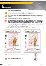
5.6.4 - Using the load capacity chart
To identify the appropriate load capacity table, refer to the icons (representing the
attachments) which appear on the table :
• To be used when lifting a load with the stabilisers raised
HTL 4010 - HTL 3210 (NA) load capacity chart stabilisers raised (Values given for information only)
Incorrect installation could result in the attachment or load disengaging, causing death or serious injury.
Make yourself familiar with the information Section E 3, Section E 4.
Use the capacity table (load chart booklet) corresponding to this attachment located in the cab (Left hand
dashboard).
The machine must not be used without the capacity chart booklet.
All the loads indicated on the nominal capacity chart (load chart booklet) assume that the machine is on
firm ground with the chassis level, the load evenly distributed on the attachments, tyres of the correct size,
sufficiently inflated and that the handler is in good working order. "Failure" to comply with these
instructions could result in death or serious injury.
Summary of Contents for HTL 3210
Page 2: ...2 2420344510 E 11 11 AUS Telescopic handlers...
Page 12: ...12 2420344510 E 11 11 AUS Telescopic handlers...
Page 74: ...74 2420344510 E 11 11 AUS Telescopic handlers D Operation...
Page 80: ...80 2420344510 E 11 11 AUS Telescopic handlers E Attachments HTL4010 load capacity chart...
Page 146: ...146 2420344510 E 11 11 AUS Telescopic handlers F Emergency procedure...
Page 159: ...159 2420344510 E 11 11 AUS Telescopic handlers H Lubrication and maintenance...


