5 Operate
17
5.2.3
Monitoring the thermal protection
Requirement:
Connect the monitoring of the thermal protection switch via the
signal line K1 UL to pin 4 and 5 of the K1 signal socket.
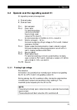
Pin 4 is an open collector
output.
A +12 to +24 V
DC
B 1 to 10 k
Ω
C PLC connection
D GND
If the device functions properly,
a signal (low level) is applied to
pin 4. The internal resistance is
500
Ω
and the reference ground (GND) is applied to pin 5.
Depending on the voltage input, a signal b12 to +24 V
DC
is
applied when the thermal protection is switched off. The HV is
switched off and the “Reset” button flashes. Before activating the
“Reset” button, the discharging power pack must be cooled down
(approx. 15 minutes). After the reset, the HV is switched on again
and the signal (low level) is again applied.
5.2.4
External reset
Precondition:
Connection of a potential-free normally open contact via signalling
line K1 UL to Pin 5 and 6 of signalling socket K1.
After the high voltage has been switched off as a result of an error, it
can be switched back on again by means of the potential-free
normally open contact. For an external reset, the potential-free
normally open contact must be closed for approx. 1 second.
NOTE:
The external normally open contact must be a potential-free normally
open contact.
For a reset, the potential-free normally open contact must be closed
for approx. 1 second.
Summary of Contents for 01.7924
Page 2: ......
Page 27: ......
Page 28: ...EN 9 Sine UL v01gb docx V01 28 01 2021 D 0406 GB made by...


