NetWave DirectView Broadcast Console Operations & Technical Manual
Revision A
2 - Installation
Harris Broadcast
2-6
PR&E
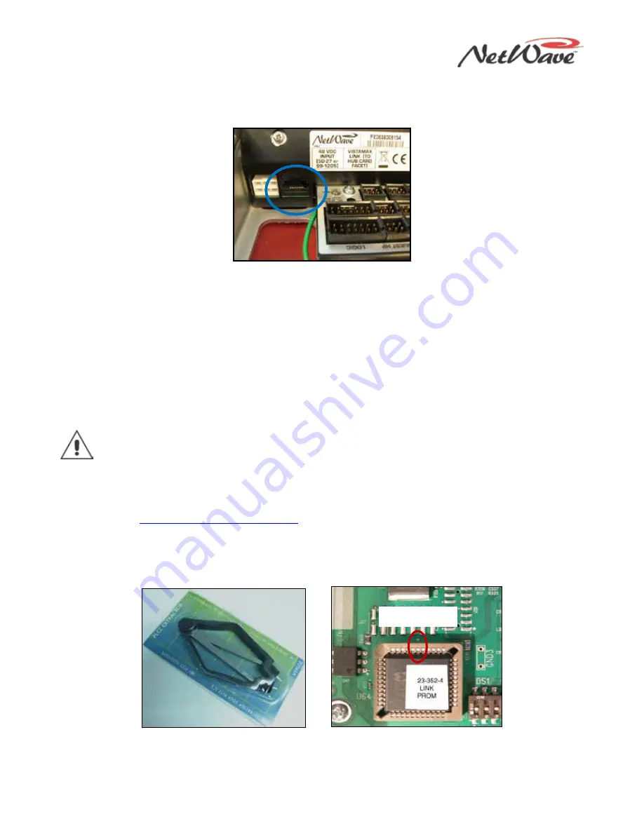
The NetWave console’s RJ-45 Link jack (Figure 2-8) is next to the keyed DC power connector on the rear
panel. The jack connects the console to any available VistaMax Hub card facet using a cross-over CAT-5e or
CAT-6 cable (customer supplied). The maximum length of a Link cable is 330 feet [100 meters].
Figure 2-8. RJ-45 Link Jack
Link or Link Plus activation adds these capabilities to the NetWave console:
●
A routed (or network) signal can be set as either the A or B source on any fader channel.
●
A routed signal can be used instead of the local Ext In 1 and/or Ext In 2 monitor input.
●
Various console buses (four programs, two mix-minuses, Telco record, and stereo cue) plus one local
audio input (either analog or digital) from each channel can be a network source, available for routing to
any VistaMax destination.
●
Link Plus Activation adds four more network-only Telco mix-minus signals. On a NetWave-24 console,
these signals replace the source signals normally available from audio inputs 21–24.
To install either activation kit, you must power off the console and remove the Monitor Control panel.
Note: Discharge possible static charges before performing this procedure or handling any PROM.
Activation Kit Installation
1.
Power down the console.
2.
Control Panel Removal Procedure
to remove the Monitor Control panel.
3.
Use the PLCC Extraction Tool (Figure 2-9), included in the Activation kit, to remove PROM U64
(Figure 2-10) from the front left corner of the Monitor & Output card:
a.
Place the two tool tips into the open corners of the PROM.
b.
Squeeze the tool handles to “pop” the PROM out of the socket.
Figure 2-9. PLCC Extraction Tool
Figure 2-10. PROM U64
4.
Place the Link PROM (21-352-4) or Link Plus PROM (21-352-6) into the U64 socket, aligning the Pin 1
mark on the PROM to the circuit board mark. Firmly press on the PROM to fully seat it into the socket.
Pin 1 Marks


