Installation and Wiring
EIO0000001505 12/2014
109
Special Functions
Description
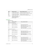
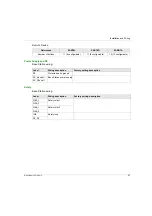
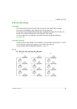
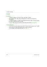
The Wireless Remote Control System manages 4 specific relays:
You can configure the specific relays with the eXLhoist Configuration Software
.
Application Example
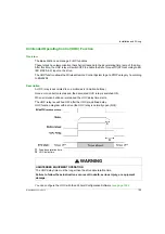
A “Radio link” indication shall inform operator about the system communication status according
to EN 15011 standard.
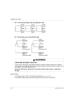
It is recommended to use a Schneider Electric beacon:
1
Light wired to the “Radio link” relay
2
Light wired to the “Safety relay image” relay
3
Buzzer wired to the “Horn” relay (an additional flash light can be wired to this relay)
The beacon operating is described in the START mode description
.
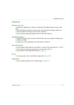
Relay
Description
Horn
This relay is switched ON during the start procedure, and for a configurable duration.
This relay is also switched ON, in START mode, as long as the ON/START/Horn is pressed.
Radio link
This relay is switched ON as long as a RADIO communication is achieved between the Base
Station and its Remote Device.
Safety relay
image
This relay is switched ON as long as the 2 safety relays are ON.
It occurs only in START mode and if all the safety conditions are fulfilled.
It can indicate when the motions are enabled.
Tandem 1+2
This relay is switched ON only in TANDEM configuration and only when the 2 Base stations
are selected.
This relay can be used in case of inhibition of anticollision in TANDEM configuration.
Summary of Contents for eXLhoist
Page 12: ...12 EIO0000001505 12 2014...
Page 34: ...Wireless Remote Control System 34 EIO0000001505 12 2014...
Page 52: ...52 EIO0000001505 12 2014...
Page 146: ...Using The Wireless Remote Control System 146 EIO0000001505 12 2014...
Page 200: ...eXLhoist Configuration Software 200 EIO0000001505 12 2014...
Page 213: ...EIO0000001505 12 2014 213 Harmony eXLhoist EIO0000001505 04 2014 Appendices...
Page 214: ...214 EIO0000001505 12 2014...

