


Chapter 2 System Installation with the Content-
Server 4000 Series
© 2017 Harmonic Inc. All rights reserved.
58
Harmonic MediaGrid Release 4.1
Connecting the Harmonic MediaGrid 4000 System Components
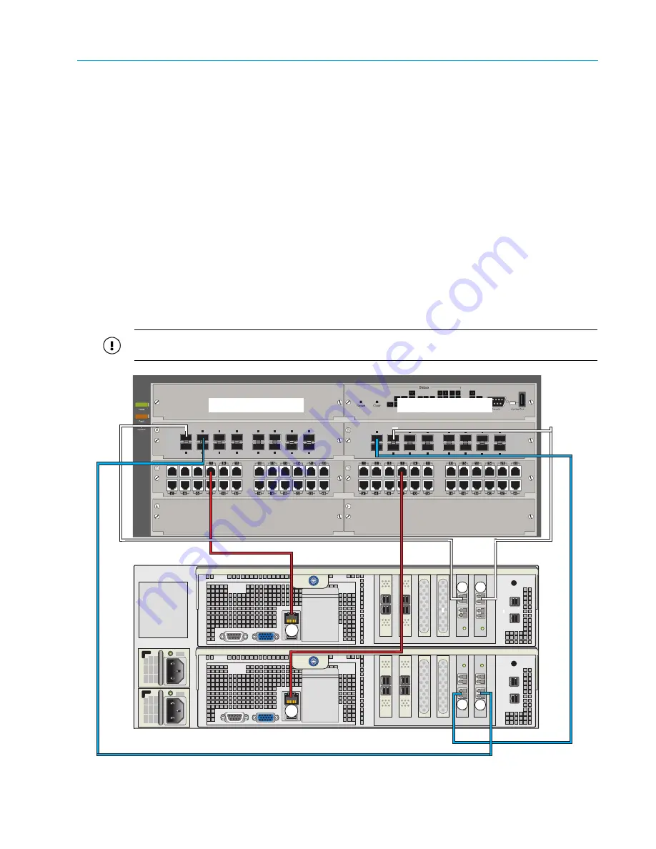
Connecting the ContentServer 4000 to the Network Switch (lower ports)
1. Starting with Controller A, connect a red CAT-6 Ethernet cable to the BMC port (maximum
data rate 100Mb/s). Connect the other end of the cable to an open port on the first 1 GbE
switch module.
2. Using a white 10 GbE SFP+ cable, connect NIC 4 on Controller A to an open port on the first
10 GbE switch module.
3. Using a white 10 GbE SFP+ cable, connect NIC 2 on Controller A to an open port on the
second 10 GbE switch module.
4. On Controller B, connect a red CAT-6 Ethernet cable to the BMC port (maximum data rate
100Mb/s). Connect the other end to an open port on the second 1 GbE switch module.
5. Using blue 10 GbE SFP+ cables, connect NIC 5 on Controller B to an open port on the
second 10 GbE switch module.
6. Using blue 10 GbE SFP+ cables, connect NIC 3 on Controller B to an open port on the first
10 GbE switch module.
7. Continue connecting the remaining ContentServers in the same manner.
8. If you are using a ContentStore 5840 or 5840A, connect all 8 10 GbE ports.
IMPORTANT:
To ensure redundancy and proper failover in the event of a failure, you must connect each
controller to a separate switch or switch module.
Figure 2–19: Connecting the ContentServer 4000 to the Network Switch (lower ports)
3
4
5
6
7
8
1
2
11
12
13
14
15
16
9
10
10-GbE SFP+ Ports
3
4
5
6
7
8
1
2
11
12
13
14
15
16
9
10
10-GbE SFP+ Ports
Controller A
Controller B
10 GbE Module A
10 GbE Module B
2
3
4
5
BMC
BMC


