background image

Chapter 11 DSNG Configuration 

 © 2013 Harmonic Inc. Harmonic All rights reserved.

318

Ellipse 3000 Release 3.0, Rev. B

Common Modulation Parameters

11.4.4

Modulation Scheme

The Modulation Scheme parameter sets the modulation scheme.

The available options are:

DVB-S

 – Modulation Scheme is set to DVB-S

DVB-S2

 – Modulation Scheme is set to DVB-S2

NOTE:  

The DVB-S2 modulation scheme is available upon permission and is not supported without a working, 

authorized, correct code.

The Modulation Scheme default is 

DVB-S2

.

Front Panel

To set the Modulation Scheme parameter on the front panel:

Navigate 

Root > IF 

or

 L-Band Modulation > Scheme

.

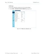
Web Manager

To set the Modulation Scheme parameter in the Web Manager:

Select 

DSNG > MODULATOR AND UPCONVERTER

 (see Figure 11–2 or Figure 11–3).

 Modulation Scheme 

‚ DVB-S

ƒ DVB-S2

Summary of Contents for Ellipse 3000

Page 1: ...Ellipse 3000 RELEASE 3 0 User Guide Rev B...

Page 2: ...ss any third party or free or open source software separately licensed to you Third Party Software If you do not agree to this Agreement you shall promptly return the System with a dated receipt to th...

Page 3: ...ted Warranty all provisions of this Agreement shall survive termination of this Agreement Upon any such termination you shall certify in writing such termination and non use to us 9 EXPORT CONTROL You...

Page 4: ...use physical harm to you NOTE The Note symbol calls your attention to additional information that you will benefit from heeding It may be used to call attention to an especially important piece of inf...

Page 5: ...Set up Procedure 29 DVB S2 L Band Modulator Setup Procedure 31 MPEG 2 Analog Transport Stream and VBI Configuration 33 Chapter 3 Ellipse Management 38 Ellipse Management Interfaces 38 Ellipse Front P...

Page 6: ...ite Delivery Descriptor Sub Menu box 111 DPI Sub Menu Tab 112 Chapter 5 Video Configuration 114 Input Sub Menu Box 117 Input Format 119 Analog Interface Sub Menu box 120 Ancillary Data Sub Menu Box 12...

Page 7: ...Teletext Subtitling Activation Parameter 231 Teletext Subtitling Sub Menu Box 232 VBI Lines Even Fields and Odd Fields 234 VBI Bit Rate Calculation 237 Chapter 8 Output Interface Configuration 238 IP...

Page 8: ...Dropping Entries Web Manager 288 Alarm Sub Menu Tab 290 Redundancy Sub Menu Tab 294 Display Contrast Menu 297 Chapter 11 DSNG Configuration 298 General 298 L Band Modulator Parameters 300 Carrier 303...

Page 9: ...P 335 Logon 336 Cloning the File 337 Appendix D Audio Pass Through Schemes Set Up 339 Appendix E DS9034PCX PowerCap 340 Appendix F How to Connect an Ellipse 3000 to a Redundancy Switch343 Connecting t...

Page 10: ...13 Harmonic Inc Harmonic All rights reserved 10 Ellipse 3000 Release 3 0 Rev B Rack Mount Instructions 363 Handling Fibre Channel Cables 363 Product End of Life Disassembly Instructions 364 Safety Rul...

Page 11: ...e the encoders offer a smooth and cost effective migration path from MPEG 2 SD 4 2 0 8 bit to AVC HD 4 2 2 10 bit compression schemes making them among the most versatile contribution encoders availab...

Page 12: ...ofiles and Levels MPEG 2 MP ML MPEG 2 MP HL MPEG 4 AVC MP L4 0 MPEG 4 AVC HP L4 0 Hi422P L4 1 Video Formats PAL NTSC Video Resolutions 480i 576i 720p 1080i AUDIO Number of Channels Up to four digital...

Page 13: ...llipse 3200 DVB ASI Built in multiplexer for encoder cascading with passive loop through for cascading DVB Scrambling optional BISS mode 1 BISS E IP Output Dual GbE IP output RJ 45 auto negotiation Au...

Page 14: ...lock in band or external IF DVB S QPSK DVB DSNG QPSK 8PSK 16QAM optional DVB S2 QPSK 8PSK 16APSK optional Frequency 50 180 MHz 1 kHz steps Output Power 30 dBm to 5 dBm 0 5 dB Spurious Level 65 dBc 10...

Page 15: ...onalities that are not available when using any Ellipse front panel feature CAUTION Using PC Terminal control option can be done only by advanced users and Harmonic technical support personnel 1 3 2 R...

Page 16: ...the Save Drop key use it from any screen or menu on the front panel F2 is currently active in DSNG modules only The key sets the Carrier and Modulation Mode parameters For details see 3 1 1 1 Front P...

Page 17: ...n keys Options The currently selected option is highlighted and displayed in reverse with white characters on a black background Press ESC key to abort the selection or to return to the parent menu Pr...

Page 18: ...IN OUT Front end synchronization clock IN for external clock OUT for loop through AES EBU1 4 4x IEC 60958 AES EBU 1 4 audio inputs ANLG L R 2x Pairs of analog left right stereo inputs ASI IN1 2 2x DVB...

Page 19: ...3 Harmonic Inc Harmonic All rights reserved 19 Ellipse 3000 Release 3 0 Rev B 1 4 2 2 Ellipse 3200 Rear Panel Figure 1 4 Ellipse 3200 IF Modulator MPEG 2 H 264 CV and SD HD SDI Figure 1 5 Ellipse 3200...

Page 20: ...nterface ASI OUT1 1x DVB ASI output interface IF Out Mon IF Modulator version 1x IF Level Modulated connector for IF level output 1x L Band Monitoring connector for L Band monitoring signal L Band Out...

Page 21: ...sion Card The optional Audio Expansion Card provides the Ellipse 3000 with 8 pairs of stereo digital or analog audio input ports This card replaces the standard audio card with 2 pairs of stereo analo...

Page 22: ...r to configure the encoder using the Ellipse Web Manager 1 Connect an Ethernet cable to the MNG connector on the Ellipse Rear Panel and to a PC station or a VLAN connection 2 Power up the Ellipse and...

Page 23: ...browser 7 In the Address field of the browser enter the Ellipse IP Address in the following format http xxx xxx xxx xxx where xxx xxx xxx xxx is the IP address of the Management port Once the web mana...

Page 24: ...de of the modulator parameters For Ellipse 3200 DSNG model displays the configured Modulation and Carrier operation mode on or off as well as the Symbol Rate and TX Frequency rates of the modulator NO...

Page 25: ...econds after the most recent change During these 60 seconds the Ellipse control interfaces remind the user to save with a blinking LED the Warning LED on the front panel and a shifting background for...

Page 26: ...rface The available options are Save Sets the recently made configuration change or changes This option sets the Ellipse to act according to the new configured values Once Save is completed the Ellips...

Page 27: ...d changes For example changing the Audio Encoding Scheme from MPEG 1 Layer 2 to Dolby displays the Dolby sub menus and specific parameters in the Explorer window But the encoding affects the audio enc...

Page 28: ...following operational step by step procedures are detailed in this section H 264 Ultra Low Latency Mode Set up Procedure Setting up the output for low delay video stream using the Ellipse Web Manager...

Page 29: ...stream from the Ellipse the IRD de jitter buffer should be set to minimum To set up the Ellipse to receive and process an ultra low latency H 264 transport stream 1 Select Unit Video in the web manage...

Page 30: ...2013 Harmonic Inc Harmonic All rights reserved 30 Ellipse 3000 Release 3 0 Rev B Ellipse Set Up Procedures NOTE When using a DVB S L Band modulator the frame length is user selectable The 16 200 bits...

Page 31: ...Rate 10 000 000 symbols per second sps L Band frequency 950 000 Hz LO frequency 14 000 000 Hz Spectrum inversion Direct Carrier and Modulator operation mode C M Manual Restore 1 Navigate Root L Band...

Page 32: ...tor frequency set up menu Enter the required value 140000000 Hz and press Enter twice to confirm and return to the L Band menu 10 Check the Tx RF Freq displays the calculated RF frequency L Band LO 14...

Page 33: ...Set up Procedure This procedure uses the front panel interface It can be equally performed using the web manager interface Refer to 5 1 Input Sub Menu Box of this manual for detailed information abou...

Page 34: ...then select VBI VBI GeneraI 8 Use the PID parameter to set the VBI PID to 2000 use the alphanumeric touch pad to on the front panel to enter the value 9 Press Enter to confirm and return to VBI menu...

Page 35: ...ure This procedure uses the front panel interface It can be equally performed using the web manager interface Refer to section 5 1 2 Analog Interface Sub Menu box of this manual for detailed informati...

Page 36: ...s F1 on the front panel to save the parameters 2 2 3 3 MPEG 2 Analog New Service Configuration Set up Procedure This procedure uses the front panel interface It can be equally performed using the web...

Page 37: ...nc Harmonic All rights reserved 37 Ellipse 3000 Release 3 0 Rev B Ellipse Set Up Procedures 5 Press Enter to confirm and return to Add New menu 6 Press F1 on the front panel to save the new service re...

Page 38: ...se Series of Contribution Encoders offers the two management interfaces to the Ellipse operator Front panel interface for local management see 3 1 1 Ellipse Front Panel Control Interface Web Manager i...

Page 39: ...status LED Four Way Touch Pad Includes the Up Down Left and Right arrow keys for navigating between menus sub menus and within menu items They are also used for parameter selection and setting paramet...

Page 40: ...5jkl four times for l 4 Wait for cursor to advance to the next position 5 Press 5jkl four times for l again 6 Press 6mno four times for o 3 1 1 2 Front Panel Screen Types The front panel uses the foll...

Page 41: ...he screen default display consists of up to four items simultaneously Scroll up or down the list using the UP and Down keys Options The currently selected option is highlighted and displayed in revers...

Page 42: ...ng the UP and Down keys Options The currently selected option is highlighted and displayed in reverse with white characters over a black background Press ESC to abort the selection or to return to the...

Page 43: ...e Screen The Edit Value screen enables setting parameter value a number or a string of characters that can be written by using the alphanumeric touch pad Top Line The top line displays the parameter n...

Page 44: ...top right corner and indicate that up down scrolling is possible Numbered Items Next up to four displayed lines A numbered list of options relevant to the parameter A radio button indicates which opti...

Page 45: ...to interface with the Ellipse operator The window title bar displays the following which are also visible on the Unit System tab System Description System Name System Location Raised alarms display wi...

Page 46: ...ee Navigation Click tabs and sub tabs to navigate the Ellipse Web Manager Tab Navigation The tabs allow you to select a group of parameters equivalent to a menu in the front panel of the encoder GUI s...

Page 47: ...brackets and the available range is specified in light blue Right Side A free text field To edit the text the user must click the field once for the cursor to appear and then the user can type the re...

Page 48: ...a menu navigation screen that leads to the three main basic menus Preset Configuration and Status NOTE Ellipse 3200 DSNG Encoders feature an additional top level menu for DSNG management The menu opti...

Page 49: ...Panel Root Menu Tree Front Panel Root Menu Preset Configuration Status Ellipse 3200 L BAND Modulation and Up converter Transport Stream Video Audio Output Interface Inputs Alarm Status Access Authoriz...

Page 50: ...atus Menu Tab on page 62 The sub tabs arrayed at the top of the browser window These tabs are displayed specifically according to the selected tab Selecting a sub tab displays its general parameters a...

Page 51: ...Status Transport Video Audio Ellipse 3200 DSNG Services and PIDs Table Active Alarms Table Modulator Status Table General Services M SPTS Tables Physical Output Unit Preset Redundancy Recall Permissi...

Page 52: ...ve Current menu Allows saving the current preset as a new preset file or override an existing file see 3 3 2 Save Menu on page 55 Delete menu Allows deleting a preset file from the file list see 3 3 3...

Page 53: ...nt 2013 Harmonic Inc Harmonic All rights reserved 53 Ellipse 3000 Release 3 0 Rev B Preset Menu Web Manager To access the Preset tab in the Web Manager Select the Preset tab see Figure 3 7 Figure 3 7...

Page 54: ...ved preset files including the factory default preset The Load Preset option allows loading the selected preset file This option executes the Load command not leading to a new screen After executing t...

Page 55: ...us Override Existing menu Allows overriding an existing preset with the current parameter setup see 3 3 2 1 Override Existing Menu Specify Preset Name menu Allows saving the current parameter setup as...

Page 56: ...ing Preset menu provides the following options and parameters The Select Preset Name parameter allows the user to select a preset file to override This option lists all preset files NOTE The default f...

Page 57: ...eset filename This option displays an edit value screen that allows entering the new filename using the alphanumeric touch pad with free text In the web management enter the new filename into the free...

Page 58: ...the preset files NOTE The default factory preset file cannot be deleted The Delete Preset option allows the user to delete the selected preset file This option executes the Delete command not leading...

Page 59: ...allows the user to set the new preset filename This option displays an edit value screen that allows entering the new filename using the alphanumeric touch pad with free text In the web management ent...

Page 60: ...nnel definitions from general parameters through specific parameters relevant to a selected audio coding scheme See Chapter 6 Audio Configuration VBI Menu See Chapter 7 VBI Output Interface Menu For t...

Page 61: ...ion Menu Tree Configuration Menu Transport Stream Output Interface Tables IP Output Input SD HD SDI CV Ancillary Data DPI Unit System Licensing M SPTS Services General Video Audio Channel General Chan...

Page 62: ...der and details their basic parameters see 3 5 1 Service and PID Table on page 65 Permissions Menu Displays the list of license permitted features see 3 5 2 Permissions on page 67 Alarm Status Menu Di...

Page 63: ...ee Front Panel To access the Status menu on the front panel Navigate Root Status Status 1 Service and PID Table 2 Permissions 3 Alarm Status 4 Access Authorizations Operator Service and PID Table Acce...

Page 64: ...Chapter 3 Ellipse Management 2013 Harmonic Inc Harmonic All rights reserved 64 Ellipse 3000 Release 3 0 Rev B Status Menu Tab Web Manager Figure 3 10 Web Manager Status Section...

Page 65: ...elementary stream bit rate value in Mbps Scram Scrambling Displays whether or not the service is scrambled NOTE In the Web Manager the Element column is called Input and displays the video and the au...

Page 66: ...armonic All rights reserved 66 Ellipse 3000 Release 3 0 Rev B Status Menu Tab Web Manager To view the Services and PID table in the Web Manager see the Status section for Services and PIDs see Figure...

Page 67: ...ontribution Encoder series and states on the right column the amount of permitted features the module has see the screen example Front Panel To view the Permissions menu on the front panel Navigate Ro...

Page 68: ...ow details the severity of the alarm in this example critical the alarm type in this example Video comp 2 fault and its time of occurrence as HH MM SS 11 41 28 Web Manager To view the Alarms list in t...

Page 69: ...formation tables Topics General Sub Menu Tab Sets the general parameters of the transport stream Services Sub Menu Tab Manages the services configuration on the transport streams M SPTS Sub Menu Tab M...

Page 70: ...Drop Transport Avails Expected Unique ProgramID Duration Flag Auto Return Scrambling Mode Transport List Services Add Service Drop Service Service List Service Basic Parameters Add PID List Drop PID...

Page 71: ...Ellipse 3000 Release 3 0 Rev B Front Panel To access the Transport Stream menu on the front panel Navigate Root Configuration Transport Stream Web Manager To access the Transport tab in the Web Manag...

Page 72: ...s are see Figure 4 1 on page 70 Output Rate Sets the TS output rate see 4 1 1 Output Rate Broadcast Standard Sets the transport stream broadcasting standard see 4 1 2 Broadcast Standard Packet Length...

Page 73: ...e actual rate is the rate last configured This means that in DSNG modules with an IP or L Band modulators the actual output can be one of two settings Actual output rate is set according to the Symbol...

Page 74: ...ternal device such as a modulator implements the packet corrector in the extra 16 bytes NOTE Packet length setup is available only for units with DVB ASI output interfaces and is used only for externa...

Page 75: ...ISS E Buried ID where the scrambling key is encrypted and buried in the equipment hardware BISS E Injected ID where the scrambling key is encrypted and requires an injected identification code The Scr...

Page 76: ...nsport Stream Configuration 2013 Harmonic Inc Harmonic All rights reserved 76 Ellipse 3000 Release 3 0 Rev B General Sub Menu Tab Front Panel Scrambling mode 1 Clear 2 BISS 1 3 BISS E Buried ID 4 ISS...

Page 77: ...r to 4 2 3 TS Scrambling Management on page 83for details Stream PID management which manages the elementary streams in the service Refer to 4 2 4 Add and Drop PID on page 90 for details 4 2 1 TS Serv...

Page 78: ...en one or more unused channels are available The number of available services is set according to license permission The license permission can start from one service per video channel and up to 16 se...

Page 79: ...ices Add Service 2 Select Service Name on the Add Service screen to display an edit value screen for entering a new service name using the alphanumeric touch pad 3 Press Enter to approve the name and...

Page 80: ...Services Drop Service 2 Select Select Service to Drop to display the list of services in the stream 3 From the displayed list select the stream to drop and press Enter to approve the selection and re...

Page 81: ...l down menu for setting its scrambling state clear or scrambled see example in Figure 4 3 The menu provides access for setting up the basic parameters of the selected service Service Name Defining the...

Page 82: ...t panel Navigate Root Configuration Transport Stream Services Service List Service Name Web Manager To access the Service Configuration menu in the Web Manager Select Transport Services Service Name s...

Page 83: ...n to the Transport Stream menu according to the scrambling mode activated specific sub menu on the front panel and the web manager BISS 1 to set a scrambling key which is clear i e not encrypted refer...

Page 84: ...for the selected service The list details the elementary stream s PID number Once the stream is selected the 2 Select Mode option in the Scrambling Menu sets the scrambling mode for the selected elem...

Page 85: ...nu Tab NOTE When setting a scrambled elementary stream to Clear mode a warning message is displayed requesting the user confirmation to clear access to the stream Setting the stream PID to scrambled s...

Page 86: ...ing key NOTE The scrambling word key values for the BISS 1 scrambling mode are not displayed Changing updating these values is done as soon as the new value is saved The required value is a 12 digit s...

Page 87: ...quired value is a 16 digit scrambling key number NOTE The scrambling word key values for the BISS E Buried ID scrambling mode are not displayed Changing updating these values is done as soon as the ne...

Page 88: ...Injected ID parameter NOTE The scrambling word key values for the BISS E Injected ID scrambling mode are not displayed Changing updating these values is done as soon as the new value is saved The Enc...

Page 89: ...ansport Stream Services Service List Service Name BISS E Injected configuration Injected ID The available value is a 14 digit key defining the unit ID number The Injected ID displayed is always 000000...

Page 90: ...Add PID Menu Front Panel The Add PID menu allows adding an elementary stream to the selected service To access the Add PID menu on the front panel Navigate Root Configuration Services Service List Ser...

Page 91: ...er on the front panel Navigate Root Configuration Services Service List Service Name List Drop PID The Select PID to Drop parameter displays a list of the available elementary streams to remove from t...

Page 92: ...ementary stream Marking or clearing an elementary stream checkbox allows adding or dropping elementary streams from the selected service To set the PID List table in the Web Manager Select Transport S...

Page 93: ...tream Management The M SPTS menu sets the Ellipse transport streams managed by the encoder over the IP interface This interface can manage multiple and independent program transport streams received o...

Page 94: ...ed channels are available The number of available IP services is set according to license permission The license permission can start from one service per IP channel and up to 16 M SPTS per unit The d...

Page 95: ...Select 1 Transport Name in the Add Transport screen to display an edit value screen for entering a new stream name using the alphanumeric touch pad 3 Press Enter to approve the name and return to the...

Page 96: ...ect Transport to Drop to display the list of transports in the stream 3 From the displayed list select the MSPTS stream to drop and press Enter to approve the selection and return to the Drop Transpor...

Page 97: ...ransport Rate The rate of the stream Range 350 000 to 70 000 000 FEC Disabled only Transport ID The identification number of the stream Range 1 to 65535 FEC Disabled only Network ID The identification...

Page 98: ...ing the front panel Navigate Root Configuration Transport Stream M SPTS Transports List Stream Name Figure 4 4 Front Panel SPTS 1 menu with FEC disabled Figure 4 5 Front Panel SPTS 1 menu with FEC ena...

Page 99: ...ase 3 0 Rev B M SPTS Sub Menu Tab Web Manager To view and set up the configuration of a specific M SPTS transport stream in the Web Manager Select Transport M SPTS Stream Name see Figure 4 6 and Figur...

Page 100: ...ticast address Dst Port sets the IP destination port number The range is 01 to 65535 Type of Service sets the type of service selected for the stream The range is 0 to 0x7f hexadecimal TTL sets the TT...

Page 101: ...umn Number sets the FEC error correction column location for the stream The range is 01 to 20 The maximum matrix size is 100 FEC Row Number sets the FEC error correction row location for the stream Th...

Page 102: ...e menu to display a list of PIDs not yet attached to the stream in order to select the PID to add 3 Press Enter The menu returns to the Add PID screen displaying the selected PID 4 Select Add to add t...

Page 103: ...se 3000 Release 3 0 Rev B M SPTS Sub Menu Tab Listing Adding and Dropping an M SPTS PID Web Manager The stream PID parameters display in the Web Manager at the Transport M SPTS Stream Name in the PID...

Page 104: ...is grouped into four sub menus boxes General Sub Menu Box sets the operating mode of the Tables menu MPEG Tables Sub Menu Box sets the SI parameters in the required tables for the MPEG Service Informa...

Page 105: ...Chapter 4 Transport Stream Configuration 2013 Harmonic Inc Harmonic All rights reserved 105 Ellipse 3000 Release 3 0 Rev B Tables Sub Menu Tab Web Manager Figure 4 8 Web Manager Tables tab...

Page 106: ...g purposes The available options are MPEG Only Sends PAT PMT CAT and PCR tables Full Adds NIT SDT and TDT tables for full PSI SI service information The default is Full ISOG Carrier ID The options are...

Page 107: ...arameter sets the transport stream ID number using hexadecimal numbers The range is 0x0 to 0xFFFF Hexadecimal The Transport Stream ID default value is 0x1000 Front Panel 4 4 2 2 Network ID The Network...

Page 108: ...erval for the following tables PAT Interval The range is 50 to 500 msec The default is 450 msec PMT Interval The range is 50 to 500 msec The default is 450 msec CAT Interval The range is 50 to 100 mse...

Page 109: ...ional specific information tables required by the DVB SI The PSI SI Tables sub menu box sets the refresh interval for the following tables SDT Interval The range is 50 to 2000 msec The default is 1800...

Page 110: ...ded by the ISOG Carrier ID menu box are Carrier Identifier option which sets an identifier for the carrier free text string Telephone number option which sets the carrier telephone number Longitude op...

Page 111: ...riptor are Sat Orbital Pos The range is 0 to 180 The default is 0 West East flag The default is Western Polarization The options are Linear horizontal Linear vertical Circular left Circular right The...

Page 112: ...terial insertion The range is 1 to 500 Seconds The default is 1 Duration Flag Indicates the presence of a duration break when set to 1 Options 0 or 1 radio button selection The default is 0 Auto Retur...

Page 113: ...isplayed for viewing Selecting an option enables the user to configure the parameter Web Manager To access the DPI sub menu in the Web Manager Select Transport DPI see Figure 4 9 Figure 4 9 Web Based...

Page 114: ...Sub Menu Box Ancillary Data Sub Menu Box Filters Sub Menu Box Encoding Sub Menu Box Bitrate Sub Menu Box Advanced Sub Menu Box Front Panel To access the Video menu using the front panel Navigate Root...

Page 115: ...n 2013 Harmonic Inc Harmonic All rights reserved 115 Ellipse 3000 Release 3 0 Rev B NOTE The Analog Interface parameters are only available for CV inputs See Figure 5 2 for the front panel video confi...

Page 116: ...ation Resolution Entropy Coding Latency Control Input Encoding Profile GOP Structure GOP Length IDR Interval Level Output on Video Loss Ancillary Data Filters Bitrate Advanced Physical Input Input For...

Page 117: ...igure 5 3 Input box Use the Input sub menu or box to display or configure the following video related parameters Video source Use the Video Source parameter to set the type of test pattern display fro...

Page 118: ...zation to the internal Ellipse clock user configured an external synchronization clock source or to Genlock Select the sync mode from the following options Internal Clock Clock source is internal the...

Page 119: ...that is available only for NTSC The encoder displays a Dependency Check error message and maintains the previous video format the user must set all values to fit the new format and then automatic sett...

Page 120: ...gain applied to the luminance signal This parameter influences the contrast of the picture the larger the gain the higher the contrast The range is 0 to 255 Default value is 128 Luminance Offset The L...

Page 121: ...e black level of the analog video signal NOTE Setup level is relevant only for NTSC format The available options are On Black level is higher than Blank level Default Off Black level is equal to Blank...

Page 122: ...WSS sent with the video input signal When this parameter is set to WSS the Aspect Ratio parameter displays the values Auto 4 3 and Auto 16 9 instead of 4 3 and 16 9 AFD Aspect Ratio Use the Aspect Ra...

Page 123: ...Default 4 3 pillarbox 1001 16 9 full frame 1010 14 9 pillarbox 1011 4 3 pillarbox alternative 14 9 center 1101 16 9 full frame alternative 14 9 center 1110 16 9 full frame alternative 4 3 center 1111...

Page 124: ...g temporal filters along motion trajectories Options Disabled Enabled Deblocking Filter If the coding format is MPEG 2 see Codec Profile this parameter is hidden A deblocking filter is applied to macr...

Page 125: ...he Encoding sub menu box comprises Activation Use to enable or disable encoding Options Disabled Enabled Default PID The PID parameter sets the video channel elementary stream PID number The range is...

Page 126: ...uto Detect then Bitrate Mode is set automatically Options Manual Set the bitrate using the Bitrate parameter Maximize Video Use the maximum possible video rate If there is no DSNG and the video is con...

Page 127: ...r settings they are hidden Sync Mode should be set to Internal Clock Low Use this option to set latency to low The latency is close to 850 msecs See Table 5 1 for Low Latency parameter settings The us...

Page 128: ...reen Only the available options display The options are NTSC 480Vx 720H Default PAL 576V x 720H Full D1 Default 720p x 1280 1080i x 1920 NTSC 480Vx 704H PAL 576V x 704H MPEG 2 Only 720p x 960 1080i x...

Page 129: ...o Video Bitrate Web Manager The Bitrate sub menu box comprises Bitrate When Bitrate Mode is set to Maximize Video and Activation is set to Enabled then you cannot set this parameter and it displays th...

Page 130: ...Advanced sub menu box to set advanced picture optimizing and compressing parameters When Latency Control is not set to Manual then you cannot set any of the advanced parameters and their values are p...

Page 131: ...re Latency Control must be set to Manual to be able to configure this parameter The Group of Pictures GOP Structure parameter sets the GOP reference frame structure This parameter determines how frequ...

Page 132: ...Latency Control must be set to Manual to be able to configure this parameter The MPEG 4 AVC SD HD Instantaneous Decoding Refresh IDR Interval parameter defines the number of GOPs interval where the ID...

Page 133: ...ual in other words they operate in pairs 1 and 2 3 and 4 5 and 6 and 7 and 8 When setting the coding scheme of one channel the user must set its partner to the same coding scheme This means that when...

Page 134: ...le menus are see Figure 6 2 General menu Holds general configuration parameters required for managing the audio stream such as coding scheme source volume and so on see 6 2 Audio General Menu Channel...

Page 135: ...Harmonic Inc Harmonic All rights reserved 135 Ellipse 3000 Release 3 0 Rev B General Web Manager To access the Audio menu in the Web Manager Select the Audio tab see Figure 6 1 Figure 6 1 Audio Config...

Page 136: ...x Input Level Source Coding Scheme Volume Test Tone PID Activation Language Audio Coding Schemes MPEG 1 Layer 2 DD 2 0 MPEG 2 AAC LC MPEG 4 HE AAC Audio Pass Thru Schemes Dolby Digital Pass Through Do...

Page 137: ...eters These parameters such as coding scheme audio source test and so on are generic and common to all supported coding schemes Front Panel To access the General menu on the front panel Navigate Root...

Page 138: ...ers DD 2 0 Sets the coding scheme of the audio channel to Dolby Digital 2 0 enabling the Dolby Digital 2 0 Configuration menu See 6 5 2 Dolby Digital 2 0 Parameters and 6 5 3 Dolby Digital 2 0 and Dol...

Page 139: ...parameter on the front panel Navigate Root Configuration Audio Audio Channel General Coding Scheme Web Manager To set the Audio Coding Scheme parameter in the Web Manager Audio General menu Select Au...

Page 140: ...ons available for the odd channel NOTE The Embedded source is currently supported only for SDI video interface and is displayed as Not Available for a CV video interface However even when setting the...

Page 141: ...Aud 6 2 3 Test Tone The Test Tone parameter sets the audio pattern source self test mode of operation The Audio test simulates 1 kHz test tone input The available options are Off Deactivates the audio...

Page 142: ...is valid only when the audio source is analog When the audio source is set to Digital or Embedded Not Available this parameter is available but does not affect the audio encoding The full audio path i...

Page 143: ...LR the maximum power of 18 dBu On the decoder side there is no option to control the analog gain However there is an option to set digital attenuation up to 60 dB Summary The Ellipse Max Input Level p...

Page 144: ...3 0 Rev B Audio General Menu Front Panel To set the Max Input Level parameter on the front panel Navigate Root Configuration Audio Audio Channel General Max Input Level Web Manager To set the Max Inpu...

Page 145: ...en the audio source is set to Dolby or Embedded Not Available this parameter is available but does not affect the audio encoding The available options are 600 ohm Impedance is set to 600 High Impedanc...

Page 146: ...number activation mode and language are generic and common to all supported coding schemes Front Panel To access the Channel Parameters menu on the front panel Navigate Root Configuration Audio Audio...

Page 147: ...led Audio channel is disabled Enabled Audio channel is enabled and active The Activation default value for the first channel is Enabled The other channels are disabled by default Front Panel To set th...

Page 148: ...Menu 6 3 2 PID The PID parameter sets the audio channel PID number The range is 32 to 8190 Front Panel To set the PID parameter on the front panel Navigate Root Configuration Audio Audio Channel Chann...

Page 149: ...as the language code number 3 characters according to ISO 639 2 standard The available values are 0 No specific language has been set XXX 3 characters represent the language code according to the ISO...

Page 150: ...wing the user to set embedded audio source definitions These definitions consists of two parameters Group Channels First select the audio channel group Each group has four audio channels pairs 1 2 and...

Page 151: ...Ellipse 3000 Release 3 0 Rev B SDI Embedded Parameters Front Panel To access the Embedded Parameters menu on the front panel Navigate Root Configuration Audio Audio Channel Embedded Params Figure 6 4...

Page 152: ...ded parameters in the Web Manager Select Audio Aud The following box displays when you select any Coding Scheme except Cue Tone and Dolby Digital 5 1 Figure 6 5 Embedded box The following boxes displa...

Page 153: ...l for each Dolby Digital 5 1 channel set Navigate Root Configuration Audio Audio Channel L R DD 5 1 Embedded Params Group Select the group Navigate Root Configuration Audio Audio Channel C LFE DD 5 1...

Page 154: ...3 0 Rev B SDI Embedded Parameters To set the Group parameters in the Web Manager for each Dolby Digital 5 1 channel set 1 Select Audio Aud 2 Select groups for the following 3 boxes DD 5 1 L R Embedde...

Page 155: ...olby Digital 5 1 channel set group Navigate Root Configuration Audio Audio Channel L R DD 5 1 Embedded Params Channel Select the channel Navigate Root Configuration Audio Audio Channel C LFE DD 5 1 Em...

Page 156: ...o the common General and Channel Parameter s menus also holds one or two specific configuration menus These menus are dynamic and displayed according to the selected coding scheme of the audio channel...

Page 157: ...ws setting analog audio parameters specific for MPEG 1 Layer 2 audio encoding scheme NOTE The coding scheme of the selected audio channel must be set to MPEG 1 Layer 2 Front Panel To access the MPEG 1...

Page 158: ...monic All rights reserved 158 Ellipse 3000 Release 3 0 Rev B Coding Scheme Configuration Web Manager To access the MPEG 1 layer 2 Parameters menu in the Web Manager Select Audio Aud The following sect...

Page 159: ...o independent channels carrying the same audio PIDs Stereo Encoding mode is set to stereo for encoding a stereophonic audio signal Joint Stereo Encoding mode is set to joint stereo Joint stereo is use...

Page 160: ...incoming audio quality of the audio input element device A D digital receiver The available options are 32 kHz 44 1 kHz 48 kHz The MPEG 1 Layer 2 Sample Rate default value is 48 kHz Front Panel To set...

Page 161: ...utput rate must be set to a high rate minimum of 384 000 bps If the rate is not high enough the encoder will display a Dependency Check message For more information about Latency Control see 5 4 1 Lat...

Page 162: ...ther negative or positive where negative values cause video delay and positive values cause audio delay The MPEG 1 Layer 2 A V Delay Offset range is 300 to 300 msec Default value is 0 Front Panel To s...

Page 163: ...vailable options are Off Error protection detector is disabled On Error protection detector is enabled and active The MPEG 1 Layer 2 Error Protection default value is Off Front Panel To set the Error...

Page 164: ...opy of an original bit stream The available options are Off The bit stream is a copy of an original bit stream On The bit stream is an original bit stream The MPEG 1 Layer 2 Original Mark default is O...

Page 165: ...rotection laws The available options are Off The information is not protected by copyright On The information is protected by copyright The MPEG 1 Layer 2 Copyright Mark default is Off Front Panel To...

Page 166: ...ed by monitoring the pre emphasis flags within the channel status data of the incoming digital audio signal On Detection mode of operation is enabled The audio signal is constantly de emphasized Off D...

Page 167: ...g of digital audio input NOTE This parameter must always be set to Ignore The available options are Ignore and Detect The MPEG 1 Layer 2 User Bit default is Ignore Front Panel To set the User Bit para...

Page 168: ...g scheme NOTE The coding scheme of the selected audio channel must be set to DD 2 0 The Dolby Digital 2 0 coding scheme is available only upon license permission Front Panel To access the Dolby Digita...

Page 169: ...c Harmonic All rights reserved 169 Ellipse 3000 Release 3 0 Rev B Coding Scheme Configuration Web Manager To access the DD 2 0 Parameters menu in the Web Manager Select Audio Aud The following section...

Page 170: ...to single mono channel Mono channel is always left Stereo Encoding mode is set to stereo for encoding a stereophonic audio signal The DD 2 0 Encoding mode default value is Stereo Front Panel To set th...

Page 171: ...nput element device A D digital receiver The available options are 32 kHz The sample rate is set to 32 kHz 44 1 kHz The sample rate is set to 44 1 kHz 48 kHz The sample rate is set to 48 kHz The DD 2...

Page 172: ...ble Encoding mode The Output Rate default value is 192 Kbps NOTE When setting the latency control parameter to low delay the audio output rate must be set to a high rate minimum of 384 Kbps If the rat...

Page 173: ...y can be either negative or positive where negative values cause video delay and positive values cause audio delay The DD 2 0 A V Delay Offset range is 300 to 300 Default value is 0 Front Panel To set...

Page 174: ...available options are Not Indicated Surround indicator is disabled No Surround Indicated Audio input signal is not surround coded Surround Coded Audio input signal is surround coded The Dolby Digital...

Page 175: ...s exist within the Dolby Digital 2 0 encoded bit stream The available options are On Off The DD 2 0 Production Info Exist default is Off disabled Front Panel To set the Production Info Exist parameter...

Page 176: ...the Dolby Digital 2 0 encoding scheme Thus the program can be replayed at the same loudness or at a known difference from the original The DD 2 0 Mixing Level range is 80 to 111 dB Default is 105 dB F...

Page 177: ...ot Indicated Room type is not indicated Large Room X Curve Monitor Room type is large Small Room Flat Monitor Room type is small The DD 2 0 Room Type default is Small Room Flat Monitor Front Panel To...

Page 178: ...not the bit stream is a copy of an original bit stream The available options are Off The bit stream is a copy of an original bit stream On The bit stream is an original bit stream The DD 2 0 Original...

Page 179: ...as protected by copyright The available options are Off The information is not protected by copyright On The information is protected by copyright The DD 2 0 Copyright Mark default is Off Front Panel...

Page 180: ...earing Impaired Dialog Commentary Emergency Voiceover Mono or Karaoke stereo The DD 2 0 Bit Stream Mode default is Complete Main Front Panel To set the DD 2 0 Bit Stream Mode parameter on the front pa...

Page 181: ...are 1 to 31 which are interpreted as 1 to 31 dB with respect to digital 100 This parameter affects the sound reproduction level The DD 2 0 Dialog Normalization range is 31 to 1 dB Default value is 27...

Page 182: ...the selected audio channel must be set to DD 2 0 or DD 5 1 The Dolby Digital 2 0 and DD 5 1 coding schemes require licenses Front Panel To access the Pre Processing menu on the front panel Navigate R...

Page 183: ...pass filter mode of operation The available options are Off Low pass filter is disabled On Low pass filter is enabled The Dolby Pre Processing Low Pass Filter default is On Front Panel To set the Dol...

Page 184: ...by Pre Processing audio encoding scheme The available options are Off DC high pass filter is disabled On DC high pass filter is enabled The Dolby Pre Processing DC High Pass Filter default is On Front...

Page 185: ...set the RF Over Modulation Protection parameter on the front panel Navigate Root Configuration Audio Audio Channel Pre Processing RF Overmodulation Protection Web Manager To set the Dolby Pre Process...

Page 186: ...phase shift Web Manager To set the 90 Degree phase shift parameter in the Web Manager Select Audio Aud and access the Pre Processing parameters box 6 5 3 6 3dB Attenuation Use this parameter to reduce...

Page 187: ...c range compression algorithm Each profile has its own boost null band and cut parameters The available options are None Film Standard Film Light Music Standard Music Light Speech The Dolby Pre Proces...

Page 188: ...l must be set to MPEG 2 AAC LC The MPEG 2 AAC LC coding scheme is available only upon license permission Front Panel To access the MPEG 2 AAC LC Parameters menu on the front panel Navigate Root Config...

Page 189: ...de is set to single mono channel always left channel Stereo Mid Side OFF Stereo Mid Side ON The MPEG 2 AAC LC Encoding mode default is Stereo Front Panel To set the MPEG 2 AAC LC Encoding Mode paramet...

Page 190: ...e incoming audio quality of the audio input element device A D digital receiver The available options are 32 44 1 48 kHz The MPEG 2 AAC LC Sample Rate default value is 48 kHz Front Panel To set the MP...

Page 191: ...Output Rate for each available Encoding mode The MPEG 2 AAC LC Output Rate default value is 48 Kbps NOTE Latency control parameter at low delay is not supported for MPEG 2 AAC LC If selected Dependen...

Page 192: ...negative values cause video delay and positive values cause audio delay The MPEG 2 AAC LC A V Delay Offset range is 300 to 300 in msec Default value is 0 msec Front Panel To set the MPEG 2 AAC LC A V...

Page 193: ...nnel must be set to MPEG 4 HE AAC The MPEG 4 HE AAC coding scheme is available only upon license permission Front Panel To access the MPEG 4 HE AAC Parameters menu on the front panel Navigate Root Con...

Page 194: ...e MPEG 4 HE AAC Encoding mode available options are MPEG 4 HE AAC v1 and MPEG 4 HE AAC v2 The default is v1 Front Panel To set the MPEG 4 HE AAC Encoding Mode parameter on the front panel Navigate Roo...

Page 195: ...Mono Encoding mode is set to single mono channel Mono channel is always left Stereo Encoding mode is stereo The MPEG 4 HE AAC Encoding mode default is Stereo Front Panel To set the MPEG 4 HE AAC Enco...

Page 196: ...coming audio quality of the audio input element device A D digital receiver The available options are 32 kHz 44 1 kHz 48 kHz The MPEG 4 HE AAC Sample Rate default value is 48 kHz Front Panel To set th...

Page 197: ...PEG 4 HE AAC Output Rate default value is 48 Kbps NOTE Latency control parameter at low delay is not supported for MPEG 4 HE AAC If selected the encoder will display a Dependency Check message For mor...

Page 198: ...e or positive where negative values cause video delay and positive values cause audio delay The MPEG 4 HE AAC A V Delay Offset range is 300 to 300 The default value is 0 Front Panel To set the MPEG 4...

Page 199: ...use the optional Audio Expansion Card See 1 4 2 3 Optional Audio Expansion Card See Figure 6 10 for Dolby Digital 5 1 speaker positions Figure 6 10 Dolby Digital 5 1 speaker positions The Dolby Digit...

Page 200: ...nnels are reserved automatically therefore AUD2 AUD3 if you selected AUD1 and AUD6 AUD7 if you selected AUD5 3 Select the General menu 4 Select the Coding Scheme menu 5 Select DD 5 1 6 Press F1 to sav...

Page 201: ...ault audio video delay is 0 milliseconds Production Info Exist DD 5 1 Use this parameter to enable or disable the inclusion of the Mixing Level and Room Type parameters in the Dolby Digital 5 1 encode...

Page 202: ...the following On Off The Copyright mark default is On Bitstream Mode DD 5 1 Use this parameter to indicate the type of audio service that the Dolby Digital 5 1 encoded bit stream transports Choose one...

Page 203: ...anel Navigate Root Configuration Audio Audio Channel DD 5 1 Parameters Figure 6 11 DD 5 1 Parameters Front Panel Web Manager To access the DD 5 1 parameters in the Web Manager Select Audio Aud DD 5 1...

Page 204: ...Chapter 6 Audio Configuration 2013 Harmonic Inc Harmonic All rights reserved 204 Ellipse 3000 Release 3 0 Rev B Coding Scheme Configuration Figure 6 12 DD 5 1 Parameters Web Manager...

Page 205: ...oost Range 53 to 41 dB 2 1 ratio Null Band Width 20 dB 41 to 21 dB Early Cut Range 26 to 11 dB 2 1 ratio Cut Range 11 to 4 dB 20 1 ratio Music Standard Boost Range 55 to 31 dB 2 1 ratio Null Band Widt...

Page 206: ...the Dynamic Range Control parameters menu on the front panel Navigate Root Configuration Audio Audio Channel Dynamic Range Control Figure 6 13 Dynamic Range Control menu Front Panel Web Manager To ac...

Page 207: ...Use this parameter to select either the Lo Ro or the Lt Rt downmix in a consumer decoder that has stereo outputs Extended BSI must be on The options are Not indicated Lo Ro Downmix Lt Rt Downmix Lt R...

Page 208: ...se this parameter to indicate to the decoder the desired level shift for the surround channels during downmixing to stereo or mono Extended BSI must be on The options are 1 5dB 3dB 4 5dB 6dB Infi dB F...

Page 209: ...Harmonic Inc Harmonic All rights reserved 209 Ellipse 3000 Release 3 0 Rev B Coding Scheme Configuration Web Manager To access the DD 5 1 parameters in the Web Manager Select Audio Aud Figure 6 16 Ex...

Page 210: ...when DD 5 1 Extended BSI is off The parameters are Center Mix Level Surround Mix Level Center Mix Level The options are 3 dB 4 5 dB 6 dB Surround Mix Level The options are 3 dB 6 dB 0 dB Front Panel...

Page 211: ...hrough coding schemes the Ellipse must synchronize with the external equipment sending the audio stream see Appendix D Audio Pass Through Schemes Set Up NOTE The coding scheme of the selected audio ch...

Page 212: ...annel already encoded in the Dolby Digital coding scheme The Dolby Digital Pass Through Encoding mode default is Stereo Front Panel To set the DD Pass Through Encoding Mode parameter on the front pane...

Page 213: ...g scheme This parameter is used to define the incoming audio quality of the audio input element device A D digital receiver The Dolby Digital Pass Through Sample Rate default value is 48 kHz Front Pan...

Page 214: ...ue is 192 Kbps The following table details the available values of the DD Pass Through Output Rate for each available Encoding mode NOTE When setting the latency control parameter to low delay the aud...

Page 215: ...re negative values cause video delay and positive values cause audio delay The range is 300 to 300 msec The DD Pass Through A V Delay Offset default is 0 msec Front Panel To set the DD Pass Through A...

Page 216: ...audio based transmissions such as radio stations and so on NOTE When Ellipse transmits pass through coding schemes the Ellipse must be synchronized with the external equipment sending the audio stream...

Page 217: ...y encoded in the Dolby E encoding scheme The Dolby E Pass Through Encoding mode default is Stereo Front Panel To set the Dolby E Pass Through Encoding Mode parameter on the front panel Navigate Root C...

Page 218: ...the incoming quality of the Dolby E encoded audio input element device A D digital receiver The Dolby E Pass Through Sample Rate default value is 48 kHz Front Panel To set the Dolby E Pass Through Sam...

Page 219: ...lated according to 20 information bits 2 688 Mbps 24 bits Output rate is calculated according to 24 information bits NOTE When setting the latency control parameter to low delay the audio output rate...

Page 220: ...e values cause video delay and positive values cause audio delay The range is 300 to 300 msec The Dolby E Pass Through A V Delay Offset default is 0 msec Front Panel To set the Dolby E Pass Through A...

Page 221: ...stations and so on The Linear PCM Pass Through scheme allows the audio stream as is and the output rates are calculated in Mbps instead of kbps NOTE When Ellipse transmits pass through coding schemes...

Page 222: ...de of the audio channel The Linear PCM Pass Through Encoding mode default value is Stereo Front Panel To set the Linear PCM Pass Through Encoding Mode parameter on the front panel Navigate Root Config...

Page 223: ...to define the incoming audio quality of the audio input element device A D digital receiver The Linear PCM Pass Through Sample Rate default value is 48 kHz Front Panel To set the Linear PCM Pass Thro...

Page 224: ...ncoding mode The available options are 1 920 Mbps 16 bits Output rate is calculated according to 16 information bits 2 304 Mbps 20 bits Output rate is calculated according to 20 information bits 2 688...

Page 225: ...tive values cause video delay and positive values cause audio delay The range is from 300 to 300 msec The Linear PCM Pass Through A V Delay Offset default is 0 msec Front Panel To set the Linear PCM P...

Page 226: ...ions for the left and right channels Sensitivity Sets the sensitivity level Range 0 to 16 Default value 06 Activation Enables Disables the Cue Tone function Default Disabled Mode Sets the mode of oper...

Page 227: ...erved 227 Ellipse 3000 Release 3 0 Rev B Cue Tone Parameters Web Manager To access the Cue Tone parameter boxes in the Web Manager Select Audio Aud and access the Left or Right Channel Parameters box...

Page 228: ...Standard Parameter PID Parameter Activation Parameter VBI Lines Even Fields and Odd Fields Teletext Subtitling Sub Menu Box The VBI menu tab sets VBI elementary stream definitions such as PID activati...

Page 229: ...Chapter 7 VBI 2013 Harmonic Inc Harmonic All rights reserved 229 Ellipse 3000 Release 3 0 Rev B Web Manager Click VBI...

Page 230: ...se 3 0 Rev B General Sub Menu Box 7 1 General Sub Menu Box Use this sub menu box to activate and configure VBI Front Panel Web Manager 7 1 1 Video Standard Parameter Displays the video input format Ge...

Page 231: ...r In the Ellipse 3000 VBI is extracted only from the video input that is being encoded active video The range is 32 to 8190 Front Panel 7 1 3 Activation Parameter The Activation parameter sets the VBI...

Page 232: ...Disables the teletext subtitling function Subtitling Page 0 1 2 3 Additional Information Program Schedule options Sets the page number The range is 100 to 899 Subtitling Page 0 1 2 3 Additional Inform...

Page 233: ...Chapter 7 VBI 2013 Harmonic Inc Harmonic All rights reserved 233 Ellipse 3000 Release 3 0 Rev B Teletext Subtitling Sub Menu Box Web Manager Figure 7 1 Teletext Subtitling Box...

Page 234: ...SC option Lines 5 8 and 22 23 are disabled for NTSC video format When the Video Format is set to NTSC line 21 can insert Closed Caption VBI Enabling the line sends the Closed Caption through the Video...

Page 235: ...tion is captured and the interface used VBI Feature PAL 576i line NTSC 480i line Over CV Over SDI Teletext Subtitling 7 22 N A Yes Yes Closed Caption V Chip 21 encoded as Teletext 21 Yes Yes Closed Ca...

Page 236: ...Front Panel To set the odd and even values of a line on the front panel 1 Select the line 2 Select the odd or even side for value see the following example for VBI line 11 Odd Web Manager Figure 7 2...

Page 237: ...ideo formats for PAL it is 25 frames and for NTSC it is 30 frames Raw Data lines lines that are enabled as Raw Data are calculated as 18 single lines In other words a Raw Data line s bit rate is calcu...

Page 238: ...Use the following sub menus tabs on the Physical Output menu tab to configure the output interface configuration settings IP OUT Sub Menu Tab ASI OUT Sub Menu Tab Front Panel To access the Physical Ou...

Page 239: ...3 0 Rev B See Figure 8 1 for the front panel Physical Output menu tree structure Figure 8 1 Physical Output Sub Menu Tree Structure ASI Output Cleared IP Output DVB o IP 1 2 General Physical Output S...

Page 240: ...ut interface parameters and define output interfaces for IP transmission NOTE You must set the transmission of each program to a different IP address NOTE The output rate is the transport stream rate...

Page 241: ...put interface 8 1 1 DVBoIP1 2 Sub Menu box Front Panel To access the DVB over IP sub menu on the front panel Navigate Root Configuration Physical Output IP OUT General DVBoIP1 Menu Web Manager Use the...

Page 242: ...General sub menu box comprises the following parameters Activation Sets the operational status of the Encoder IP Output Options Disabled Enabled Scrambling Select Enable for scrambling The output scr...

Page 243: ...scrambling mode clear or scrambled to support encoder cascading The ASI OUT sub menu tab comprises the following General sub menu tab ASI Set the DVB ASI Output scrambling mode clear or scrambled to...

Page 244: ...menus see Figure 9 1 ASI Input Menu Allows setting the DVB ASI input interface parameters see 9 2 DVB ASI Input IP Input Menu Allows setting the IP input interface parameters see 9 3 IP Input Menu MP...

Page 245: ...erved 245 Ellipse 3000 Release 3 0 Rev B General Figure 9 1 Inputs Interface Configuration Menu Tree Structure ASI Input Serial Input Scrambling IP Input MPE Port Configuration Activation PID Inputs M...

Page 246: ...arameters of the Ellipse encoder DVB ASI input Front Panel To access the ASI Input menu on the front panel Navigate Root Configuration Inputs ASI Input Web Manager To set the Cascading parameters in t...

Page 247: ...nputs Rate The range is 0 to 50 000 000 bps The Rate default value is 32 000 000 bps 9 2 2 Activation DVB ASI Input Cascading The Activation parameter sets the cascading activation mode for the DVB AS...

Page 248: ...nfiguration The Input Interface menu contains the following sub menus IP Input MPE Configuration Menu Allows setting the MPE parameters for the IP input see 9 3 1 MPE Menu IP Input Port Configuration...

Page 249: ...parameters in the Web Manager Select Inputs IP INPUT MPE 9 3 1 1 Activation MPE IP Input The MPE Activation parameter sets the MPE activation mode Front Panel To access the Activation menu on the fro...

Page 250: ...uration Inputs IP Input MPE PID The range is 32 to 8190 Web Manager To set the MPE PID in the Web Manager Select Inputs IP Input MPE 9 3 1 3 MPE Rate IP Input MPE The Rate parameter sets the MPE rate...

Page 251: ...e MPE parameters in the Web Manager Select Inputs IP Input Port Configuration 9 3 2 1 Node IP Address IP Input Port Configuration The Node IP Address parameter sets the IP Port address The available v...

Page 252: ...2 Node Subnet Mask IP Input Port Configuration The Node Subnet Mask parameter sets the IP Port subnet mask address The available value is an IP subnet mask address xxx xxx xxx xxx Front Panel To acce...

Page 253: ...rs will cause the last character to be flushed out to the pipe before the break This mode is active if the Time Out parameter is set to any value but 0 i e non zero and the EOC is set to 256 End of Fi...

Page 254: ...Input Interface Configuration 2013 Harmonic Inc Harmonic All rights reserved 254 Ellipse 3000 Release 3 0 Rev B Serial Low Speed Data Input Menu Web Manager Figure 9 4 Serial Inputs LSD Web Managed Me...

Page 255: ...ot Configuration Inputs Serial Input LSD Activation Web Manager To access the Serial Inputs LSD set up menu in the Web Manager Select Inputs SERIAL INPUT LSD 9 4 2 LSD PID Setup Menu The range is 0X20...

Page 256: ...te parameter on the front panel Navigate Root Configuration Inputs Serial Input LSD Rate Web Manager To access the Serial Inputs LSD set up menu in the Web Manager Select Inputs SERIAL INPUT LSD 9 4 4...

Page 257: ...ow Speed Data Input Menu 9 4 5 LSD End Of File EOF Character Setup Menu The range is 0 to 256 Front Panel To access the EOF Char on the front panel Navigate Root Configuration Inputs IP Input MPE EOF...

Page 258: ...rmation The available menus and options are see Figure 10 1 Licensing menu Displays the unit ID and allows entering a permission key see 10 2 Licensing System sub menu tab Allows setting system inform...

Page 259: ...Web Manager Select the Unit tab Figure 10 1 Unit Configuration Menu Tree Structure Unit 1 1 Licensing 2 System 3 SNMP Traps 4 Alarm 5 Display contrast Licensing Device ID License Key System SNMP Traps...

Page 260: ...ng to the current license key are displayed on the Permissions screen see 3 5 2 Permissions on page 67 The License menu enables access to two sub menus Device ID Manages the unit ID number see 10 2 1...

Page 261: ...he ID number It is a unique combination between the main board characteristics and the modulator card if available Front Panel To access the Device ID menu on the front panel Navigate Root Configurati...

Page 262: ...ate Root Configuration Unit Licensing The License Key menu displays the KEY parameter The KEY parameter allows access to an edit value screen in which to insert the license key Once authorized the new...

Page 263: ...tion of the unit for hardware software and serial number Administration WEB needs PW Diagnostic Report Ethernet Port Management Menu Manages the Ethernet port Serial Port Management Menu Manages the S...

Page 264: ...Chapter 10 Unit Configuration 2013 Harmonic Inc Harmonic All rights reserved 264 Ellipse 3000 Release 3 0 Rev B Ellipse System Sub Menu Tab Figure 10 3 Web Management System tab...

Page 265: ...Panel To access the System Description menu on the front panel Navigate Root Configuration Unit System Description Web Manager To access the System menu in the Web Manager Select Unit System see Figur...

Page 266: ...ration Unit System Description System Description Web Manager To view the System Description parameter in the Web Manager Select Unit System 10 3 1 2 System Up Time The System Up Time parameter displa...

Page 267: ...er on the front panel Navigate Root Configuration Unit System Description System Contact Web Manager To set the System Contact parameter in the Web Manager Select Unit System 10 3 1 4 System Name The...

Page 268: ...Configuration Unit System Description System Location Web Manager To set the System Location parameter in the Web Manager Select Unit System 10 3 1 6 Temperature C F The two Temperature parameters di...

Page 269: ...ber SW Version Displays the software version OS Displays the operating system s version BOOT ROM Displays the Boot ROM flash device s version HW Version Displays the hardware version Front Panel To di...

Page 270: ...rement of a password for Web Manager access Diagnostic Report Use to generate a diagnostic report for field debugging Reset Device Use to reset the device 10 3 3 1 Viewing the Current Configuration Fr...

Page 271: ...1 Ellipse 3000 Release 3 0 Rev B Ellipse System Sub Menu Tab Web Manager To view the current configuration in the Web Manager Select Unit System The WEB needs PW parameter displays in the Administrati...

Page 272: ...front panel 1 Navigate the following path Root Configuration Unit Licensing 2 Select one of the following parameters Disabled Enabled 3 Press Enter Web Manager To configure the WEB Needs PW parameter...

Page 273: ...nostic Report is generated in a directory called Report in the Compact Flash memory Web Manager To generate a diagnostic report 1 Select Unit System The Administration box displays on the System tab 2...

Page 274: ...ot be compatible with the user s network and must be configured to the environment where the encoder is installed The following sections detail the Ethernet Port Management menu options and parameters...

Page 275: ...e Root Configuration Unit System Ethernet Port Management IP Address Web Manager To set the IP Address parameter in the Web Manager Select Unit System 10 3 4 2 Subnet Mask The Subnet Mask parameter se...

Page 276: ...Ethernet Management port IP address The available value is of IP address type xxx xxx xxx xxx Front Panel To set the Default Gateway parameter on the front panel Navigate Root Configuration Unit Syste...

Page 277: ...e transmit rate through the network which determines the transmit rate through stream and DVB ASI The available options are 9 600 bps 14 400 bps 19 200 bps 57 600 bps 115 200 bps The Baud rate default...

Page 278: ...oder s internal clock Selecting an option in the Date menu enables the user to set the option Year Month Day Hour Minute and Second Front Panel To access the Date menu on the front panel Navigate Root...

Page 279: ...anel Control box in the Web Manager Select Unit System 10 3 7 1 Front Panel Light On Time The Front Panel Light On Time menu sets the time interval before the front panel turns off the backlight The a...

Page 280: ...ed menu sets the enables locking the front panel keys when not in use The available options are Unlocked The front panel keys are always available default option Locked The front panel keys are locked...

Page 281: ...lable options are BOOTP Activation Enables Disables updating the encoder software using BOOTP BOOTP Retries Count Sets the number of update tries for the BOOTP before failure is declared The range is...

Page 282: ...er intervention whenever a notification event occurs Currently the Ellipse support alarms notifications and alarm cancellations known as alarmOn and alarmOff For more information about SNMP traps and...

Page 283: ...e Web Manager Interface operation Selecting an entry from the Traps Destination List displays the Trap configuration menu This menu allows setting the trap definitions such as name IP address UDP port...

Page 284: ...e represents the trap access through the Traps Destinations list Therefore it is recommended to select a name that represents the station as accurately as it can for example Room 6D or Paul s Computer...

Page 285: ...nit SNMP Traps Traps Destinations List Trap Name IP Address Web Manager To set the IP Address parameter in the Web Manager Select Unit SNMP Traps trap entry name 10 4 1 3 UDP Port The UDP Port paramet...

Page 286: ...ont Panel To set the Community parameter on the front panel Navigate Root Configuration Unit SNMP Traps Traps Destinations List Trap Name Community Web Manager To set the Community parameter in the We...

Page 287: ...host is defined with the selected Destination IP address see the previous section This option executes the Add Entry command not leading to a new screen Once the new entry is displayed in the list the...

Page 288: ...Select Entry To Drop The Drop Entry option allows deleting the selected entry from the Traps Destinations list The entry to drop is selected by the Select Entry To drop parameter see the previous sec...

Page 289: ...et information IP address and UDP port Clicking any entry displays the entry s configuration section see 10 4 1 Traps Destination List on page 283 The new entry is set with default values for the conf...

Page 290: ...ideo 1 encoding failure Any of the Video 1 through Video 4 has an actual video rate of more than 20 the configured rate Audio 1 2 3 4 Input absent Any of the Audio 1 through Audio 4 is missing When th...

Page 291: ...his alarm is triggered if more than one primary is configured with the same group ID Solution Check the other primary devices and find the one with the same Group ID and same SGID For 1 1 find two pri...

Page 292: ...set the alarm severity level using the front panel Navigate Root Configuration Unit Alarm Alarm Configuration Alarm Type Set Severity The Set Severity default value for all alarms is Information The a...

Page 293: ...Rev B Alarm Sub Menu Tab Web Manager To access the Alarm tab in the Web Manager Select Unit Alarm See Figure 10 5 Figure 10 5 Alarm Menu Display The alarm menu lists all the available alarms Next to...

Page 294: ...and the backup Ellipse 3000 is inactive You can use many redundancy pairs by using a different group number for each pair You can change the device mode but not the device state At least one critical...

Page 295: ...the backup device polls the configuration of the primary device once redundancy is applied and during operation to monitor for changes in the primary configuration The default is Primary Multicast ad...

Page 296: ...Chapter 10 Unit Configuration 2013 Harmonic Inc Harmonic All rights reserved 296 Ellipse 3000 Release 3 0 Rev B Redundancy Sub Menu Tab Web Manager...

Page 297: ...pse display contrast The range is 1 to 10 The Set contrast default value is 3 NOTE The Display Contrast parameter is currently NOT available through the Web Manager control interface To access the Dis...

Page 298: ...Ellipse platforms provide IF or L Band modulation and up converting outputs for the encoder output streams Based on the modulation mode selected for the encoder some of the parameters are unique for L...

Page 299: ...and Modulator IF L Band Common Parameters L Band Power TX RF Freq IF Up Converter DSNG Menu L Band Freq RF Converter LO Freq Remote Power 24 VDC 10 MHz Clock IF Power IF Freq L Band Monitor Freq Outpu...

Page 300: ...ency Remote Power 24 VDC parameter see 11 2 7 Remote Power 24 VDC 10 MHz Clock parameter see 11 2 8 10 MHz Clock NOTE This set of parameters is not available for IF modulator units All other parameter...

Page 301: ...L Band Modulation Up Converter L Band Modulation Up converter Carrier On L Band Power 20 Reduced L Band Power 13 0 Modulation on off Off Symbol Rate 10000000 TX RF Freq 014950000 RF Conv LO Freq 01400...

Page 302: ...ts reserved 302 Ellipse 3000 Release 3 0 Rev B L Band Modulator Parameters Web Manager To access the L Band Modulation and Up converter menu in the Web Manager Select DSNG MODULATOR AND UP CONVERTER s...

Page 303: ...ff Carrier is disabled Shortcut combination is F2 Right Operational Enable the Carrier Shortcut combination is F2 Up Reduced Enable the Carrier and use the Reduced L Band Power setting L Band only The...

Page 304: ...cally and does not require you to access the Save menu The range is 50 to 7 dBm The L Band Power default value is 20 dBm Front Panel To set the L Band Power parameter on the front panel 1 Navigate Roo...

Page 305: ...d L Band Power The unit is dBm The range is 50 to 7 dBm The Reduced L Band Power default is 20 dBm Front Panel To set the Reduced L Band Power parameter on the front panel 1 Navigate Root L Band Modul...

Page 306: ...TX RF Frequency from 14 950 000 to 15 000 000 the following value changes occur NOTE Changes to the TX RF Frequency value only affect the L Band Frequency value However the RF Conv LO Frequency can be...

Page 307: ...000 kHz Web Manager To set the RF Conv LO Frequency parameter in the Web Manager Select DSNG Modulator and Up Converter see Figure 11 2 11 2 6 L Band Frequency The L Band Frequency parameter sets the...

Page 308: ...24 VDC is embedded in the output stream The available options are Off Embedded power feeding is disabled On Embedded power feeding is enabled The Remote Power 24 VDC default value is On Front Panel To...

Page 309: ...OR physically provided from the 10 MHz REF Clock connector on the L Band front end The available options are Off 10 MHz reference clock is available from the connector On 10 MHz reference clock is ava...

Page 310: ...edance NOTE This set of parameters is not available for L Band modulator units All other parameters are common to both modulation schemes and are detailed in 11 4 Common Modulation Parameters on page...

Page 311: ...e front panel Navigate Root IF Modulation IF Modulation IF Power 8 Reduced IF Power Modulation on off Off Carrier On Symbol Rate 10000000 Spectrum Inversion Direct Modulation Scheme DVB S FEC and Modu...

Page 312: ...All rights reserved 312 Ellipse 3000 Release 3 0 Rev B IF Modulator Parameters Web Manager To access the IF Modulator and Upconverter tab in the Web Manager Select DSNG MODULATOR AND UPCONVERTER see...

Page 313: ...et the IF Power parameter on the front panel Navigate Root IF Modulation IF Power Web Manager To set the IF Power parameter in the Web Manager Select DSNG MODULATOR AND UPCONVERTER see Figure 11 3 11...

Page 314: ...r Frequency Web Manager To view the L Band Monitor Frequency parameter in the Web Manager Select DSNG MODULATOR AND UPCONVERTER see Figure 11 3 11 3 4 Output Impedance The Output Impedance parameter a...

Page 315: ...ength Operating Mode parameter see 11 4 7 Operating Mode Roll Off Factor parameter see 11 4 8 Roll Off Factor Pilot Mode parameter see 11 4 9 Pilot Mode 11 4 1 Modulation On Off The Modulation on off...

Page 316: ...output rate of the encoder This means that in DSNG modules with an IP or L Band modulators the actual output can be one of two settings either it is set according to Symbol Rate using the Modulation...

Page 317: ...be calculated by addition or subtraction For example if Spectrum Inversion is set to direct L Band frequency is 14 000 000 kHz and LO frequency is 950 000 kHz then the TX RF frequency is 14 950 000 14...

Page 318: ...VB S2 Modulation Scheme is set to DVB S2 NOTE The DVB S2 modulation scheme is available upon permission and is not supported without a working authorized correct code The Modulation Scheme default is...

Page 319: ...scheme and its available Modulation modes and FEC values Front Panel To set the FEC and Modulation parameter on the front panel Navigate Root IF or L Band Modulation FEC and Modulation see the follow...

Page 320: ...various available values according to the selected modulation scheme The available options are The selected value sets the frame length to the selected number in bits for example selecting 64 800 sets...

Page 321: ...ore After changing other Modulation parameters Carrier C and Modulation M Mode are automatically restored to recently configured and saved values C M Man Restore Carrier C and Modulation Mode M values...

Page 322: ...be received but also receives more irrelevant signals from the adjacent transmission Setting a smaller Roll off value reduces the mount of irrelevant data from the adjacent transmission but also lose...

Page 323: ...e inserted and Piloted where Pilot symbols are inserted to aid carrier synchronization NOTE This parameter is only relevant for units operating under DVB S2 modulation scheme This parameter is not ava...

Page 324: ...Resolution Horizontal SD 720 704 640 544 528 480 368 352 Vertical SD NTSC 480 240 PAL 576 288 High Definition 1080ix1920 1080ix1440 1080ix960 720px1280 720px960 720px640 Interfaces SMPTE 259M for SD...

Page 325: ...ncy Up to 50 Mbps Sync Clock Black Burst CV formats PAL NTSC Interface ITU R 624 Level 1 0 Vpp Impedance 75 unbalanced A 2 Encoder Outputs DVB ASI Outputs Physical line rate 270 Mbps Output data rate...

Page 326: ...us level range from 65 dBc at 10 dBm L band monitoring output power 45 dBm L band monitoring output frequency at current L band transmit frequency Constant Code Rate Modulation CCM Supports Pilot Mode...

Page 327: ...264 0 3 Mbps 75 Mbps 4 2 2 1 5 Mbps 100 Mbps Video Test Bar Each video input supports the Broadcast Test Pattern BAR signal emulation Audio Processing Audio encoding formats MPEG 1 layer 2 Dolby Digit...

Page 328: ...on of the following PSI SI tables PAT PMT NIT SDT EIT TDT Advanced Multiplexing Up to 8 services Encoding and multiplexing is compliant with ISO IEC 13818 MPEG 2 DVB MPEG 2 implementation guidelines D...

Page 329: ...uch Pad Remote Web management through IP interface External NMS communication using SNMP management through IP interface Software Upgrade Easy to use FTP file transfer protocol or TFTP Dry Contact Ala...

Page 330: ...439x44x489 mm WxHxD Weight 10 lbs 6 kg Power Voltage 90 260 VAC 48 VDC optional Power consumption Ellipse 3100 Up to 75W Ellipse 3200 Up to 88W Up to 100W with DC power feed to BUC Environment Temper...

Page 331: ...Appendix A Characteristics and Capabilities Phase Noise 2013 Harmonic Inc 331 Ellipse 3000 r 3 0 Rev B A 9 Phase Noise Figure A 1 IF band phase noise Figure A 2 L band phase noise...

Page 332: ...ilable through the front panel Root Configuration Unit System Version Information see 10 3 2 Version Information Menu on page 269 or the Web Manager select the Unit System tabs B 1 Ellipse Setup IP NO...

Page 333: ...ftp Ellipse IP address An Explorer window displays with the Ellipse storage contents 2 Drag the upgrade RAR file from your network folder to the Ellipse window 3 In the Web Manager select Unit System...

Page 334: ...definitions are already configured To extract the IP information of the requested encoder access the IP management menu of the encoder see 10 3 4 1 IP Address on page 275 C 2 Download Preparations Bef...

Page 335: ...FTP To open an FTP session 1 Select Root Configuration Unit Licensing The Run dialog box displays 2 Enter cmd in the combo box and click Root Configuration Unit Licensing The Terminal window displays...

Page 336: ...h the username and password both are initially empty for the encoder 2 Reply with Enter for both user and password requests NOTE If the user configures the FTP server with the username and password th...

Page 337: ...o change the directory to config 2 Enter put with the location of the new database file in the C tmp folder for example put C tmp e9k db 3 Click Enter 4 The Database cloning is divided into two parts...

Page 338: ...Appendix C Database Cloning Updating Database through FTP 2013 Harmonic Inc 338 Ellipse 3000 r 3 0 Rev B 5 Enter Bye to exit the FTP session NOTE The procedure updates only a single encoder at a time...

Page 339: ...to an external clock source see details in 5 1 Input Sub Menu Box Ellipse External Synchronization Interface The Ellipse is equipped with an external clock interface The clock is available at all tim...

Page 340: ...are stress ratings only and functional operation of the device at these or any other conditions beyond those indicated in the operational sections of the specifications is not implied Exposure to the...

Page 341: ...PCM DS9034PCX DS9034PCX 0 C to 70 C 3 0 PCM DS9034PCX DS9034I PCX 40 C to 85 C 3 0 PCM DS9034PCXI DS9034I PCX 40 C to 85 C 3 0 PCM DS9034PCXI Denotes a lead free RoHS compliant device A on the top of...

Page 342: ...d Products Inc The Dallas logo is a registered trademark of Dallas Semiconductor Corporation PACKAGE INFORMATION The package drawing s in this data sheet may not reflect the most current specification...

Page 343: ...Connecting the Devices To connect the devices 1 Connect the green MICRO COMBICON to the GPI O port of the Ellipse 3000 2 To ensure good grounding connect the green yellow grounding cable to the groun...

Page 344: ...tion of issues around the clock Table G 1 For Distribution and Delivery D D Legacy Harmonic Products Region Telephone Technical Support E mail Americas 888 673 4896 888 MPEG TWO or 408 490 6477 suppor...

Page 345: ...Delivery product software downloads site is ftp ftp harmonicinc com The Harmonic Inc Playout and Production software downloads site is ftp ftp Omneon com Updates Omneon Current The Harmonic Inc corpor...

Page 346: ...desired operation Connections between the Harmonic equipment and other equipment must be made in a manner that is consistent with maintaining compliance with FCC radio frequency emission limits Modifi...

Page 347: ...cts if the part is present This table shows those components where hazardous substances may be found in Harmonic products based on among other things material content information provided by third par...

Page 348: ...ial level of the parts is below the limit defined in SJ T1 1 363 2006 standard X SJ T11363 2006 X Indicates that the content of the toxic and hazardous substances in at least one of the homogeneous ma...

Page 349: ...ssant les limites applicables aux appareils num riques de la classe A prescrites dans le R glement sur le brouillage radio lectrique dict par le minist re des Communications du Canada EU Manufacturer...

Page 350: ...lity including amendments Class A for Digital Equipment USA Canada EN55022 EN61000 3 2 EN61000 3 3 and EN55024 Safety TUV 2006 95 EC Low Voltage Directive including amendments UL60950 1 CAN CSA C22 2...

Page 351: ...0B 2010C EMC ACMA or C Tick BELLIS KVALITET ICES CNCA or CCC KONCAR CE SII VCCI OTAN CKT INSM NEMKO GOST SABS KCC BSMI UKRTEST or UKRSERTCOMPUTER FCC STZ ICT Class A Safety IRAM BELLIS SCC CNCA or CCC...

Page 352: ...egulatory Compliance Directive s Notes ContentDirector 1000C 10000D and 2000 EMC ACMA or C Tick BELLIS KVALITET ICES CNCA or CCC KONCAR CE SII VCCI OTAN CKT INSM NEMKO GOST SABS KCC BSMI UKRTEST or UK...

Page 353: ...2003 CAN CSA C22 2 60950 1 3 Safety of Information Technology Equipment ContentServer 2122 2124 EMC FCC Part 1 5 ICES 003 CISPR 22 89 336 EEC Electromagnetic Compatibility including amendments Class A...

Page 354: ...f Information Technology Equipment EMC FCC VCCI EN CISPR 22 Class A Class A 55022 Class A Safety CSA 22 2 UL IEC EN No 60950 1 60950 1 60950 1 60950 1 Regulatory Compliance Directive s Notes CE Low Vo...

Page 355: ...2201 2202 2251 2252 and the MediaCenter Regulatory Compliance Directive s Notes CE Low Voltage Directive is 2006 95 EC EMC directive is 2004 108 EC EN 60950 1 Safety of Information Technology Equipmen...

Page 356: ...tibility EN55022 EN55024 CISPR22 Class A for Digital Equipment USA Class A for Digital Equipment Canada 89 336 EEC including amendments Emissions from Information Technology Equipment Immunity for Inf...

Page 357: ...is 2004 108 EC EMC EN55022 EN61000 3 2 EN61000 3 3 and EN55024 VCCI V 3 AS NZS CISPR22 Safety EN60950 1 EN60525 1 EN60825 2 UL60950 1 CSA C22 2 No 60950 1 Regulatory Compliance Directive s Notes CE Lo...

Page 358: ...tory Information for the ContentServer 3000 and ContentStore 3160 Danger Class 1 laser product Attention Produit laser de classe 1 Warnung Laserprodukt der Klasse 1 This equipment contains optical tra...

Page 359: ...eisungen des Herstellers WARNING This product relies on the building s installation for short circuit overcurrent protection Ensure that a fuse or circuit breaker no larger than 1 20 VAC 1 5A U S 240...

Page 360: ...ier de bas en haut en pla ant l l ment le plus lourd dans le bas Si le casier est quip de dispositifs stabilisateurs installer les stabilisateurs avant de monter ou de r parer l unit en casier WARNUNG...

Page 361: ...at all times when handling this equipment Slots and openings in the chassis are provided for ventilation Do not block them Leave the back of the frame clear for air exhaust cooling and to allow room...

Page 362: ...s so that they are not likely to be damaged Disconnect power before cleaning Do not use liquid or aerosol cleaners use only a damp cloth Dangerous voltages exist at several points in this product To a...

Page 363: ...ed Air Flow Installation of the equipment in a rack should be such that the amount of air flow required for safe operation of the equipment is not compromised Mechanical Loading Mounting of the equipm...

Page 364: ...n 10 sq cm Additional PCBA s may be present depending on the configuration 2 Inside the chassis Batteries All types including standard alkaline and lithium coin or button style batteries 1 LITHIUM COI...

Page 365: ...m the rest of the material 6 Identify and separate recyclable materials as per below examples a Scrap material to be sent to smelter s b E waste such as displays CPU s cables and wires hard drives key...

Page 366: ...Rules Recycler personnel are to wear personal protective equipment including proper eye protection proper hand protection and proper breathing protection if needed Recycler personnel shall be experie...

Page 367: ...e is scanned three times to generate three video fields the second frame is scanned twice to generate two video fields and the cadence continues Note that every fifth frame will have images from diffe...

Page 368: ...nt revision published in 2010 breaking the original document into multiple Parts Some obsolete references term it AES EBU since the EBU also published the original document in 1992 as EBU Tech 3250 AF...

Page 369: ...EG 2 MPEG 4 AAC HE AAC HE AAC v2 or Dolby Digital AC 3 AIC Audio adapter used in the Electra Ion family of encoders Can compress two stereo pairs of either analog or digital audio into either MPEG 1 l...

Page 370: ...Asynchronous Transfer Mode A high bandwidth low delay switching and multiplexing technology for delivering high speed data including digital video and audio ATSC Advanced Television Systems Committee...

Page 371: ...or chrominance information Either intentionally created for a short period of time or the result of a failure in a transmission system blanking interval The process or time period when the cathode ra...

Page 372: ...ess to certain programs on the basis of a monetary exchange In commercial applications CAS allows controlled access to proprietary programs CAT Conditional Access Table The CAT informs the receiver of...

Page 373: ...e start of active video The color burst tells the monitor how to decode the color information contained in that line of active video companion key Refers to a use of the keypad that is found on some H...

Page 374: ...the CASgenerates to scramble the program data stream CWG Control Word Generator Generates the encryption key D data link The continuous flow of information from one location to another data stream The...

Page 375: ...em over satellite to receivers at the customer end user home DCII DigiCipher 2 DCE Data Communications Equipment A device that communicates with a DTE over TIA 232 For example a modem is a DCE that se...

Page 376: ...ogy resulting in outstanding compression efficiency higher quality video and better bandwidth utilization DiviTrack complexity The average video complexity of the input video source during the samplin...

Page 377: ...Digital Rights Management DS3 A North American telephony interface standard which operates at 44 736 Mbps over 75 ohm coaxial cable See also DOM DSLAM Digital Subscriber Line Access Multiplexer DTE Da...

Page 378: ...pplication that produces the ECM messages EDH Error Detection and Handling EIA Electronic Industries Alliance A U S trade organization that was once responsible for establishing hardware interface sta...

Page 379: ...eam Ethernet A data link physical interface developed for local area networks LANs that supports transmission rates up to 10 Mbps Fast Ethernet supports transmission rates up to 100 Mbps See also 10BA...

Page 380: ...erminated at the curb and connected with coaxial cable that is usually run underground to the home FTTH Fiber to the home FTTH is an access network that delivers programming to the individual customer...

Page 381: ...NMX s through an easy to use interface It addresses the needs for consolidated network management solutions for large systems where the typical size of video compression networks has grown considerab...

Page 382: ...also companion key HPA High Powered Amplifier Provides signal amplification to feed a transmitting antenna Hz See Hertz Hz I IA Intel Architecture IDP Ingest Datapath IEC power cord A power cord manuf...

Page 383: ...the destination An IP address is a 32 bit number written in dotted decimal notation four 8 bit sections separated by periods converted from binary to decimal Each section is a number from zero to 255...

Page 384: ...eceived signal LNB Low Noise Block downconverter A combination low noise amplifier and downconverter built into one device An LNB is usually located at the center of the satellite dish LSCP Lightweigh...

Page 385: ...ut to a SMPTE 310M output MCPC Multiple Channel Per Carrier MCPC NIM An MCPC NIM provides connection with wideband communications channels It supports 15 to 30 Mbaud MDM A card for the MN20 multiplexe...

Page 386: ...f the MPEG Standards have also been prepared jointly with the ITU T MPEG 1 A family of specifications developed originally for compression of low resolution SIF video at 24 25 and 30 Hz frame rates wi...

Page 387: ...ilt into encoders N NIC Network Interface Card NIM Network Interface Module A receiver component interface to an access method such as HFC satellite or ATM NIT Network Information Table This table con...

Page 388: ...erlaced in Japan See also ATSC NVOD Near Video on Demand NVRAM Non Volatile Random Access Memory NVRAM is usually implemented using static RAM with a battery backup system which enables it to retain d...

Page 389: ...AL transmits 625 lines per frame at 25 frames per second using interlaced scanning PAT Program Association Table This table indicates the location the PID values of the transport stream packets of the...

Page 390: ...pressed in Mbps Pool Complexity A value calculated from the complexity values of the channel members of a DiviTrack pool port A port is an input to or an output from a component an adapter or a module...

Page 391: ...and socket for a two wire coaxial cable used to connect consumer audio and video components Redundancy A back up system of Harmonic components that ensures uninterruptible service in the event of a c...

Page 392: ...A component that multiplexes several MPEG 2 SPTS input streams into a single MPTS output stream RFD Repeat Field Detection A capability to detect field or frame repeats in video signals where the orig...

Page 393: ...different sources SCP Secure Copy SCPC Single channel per carrier SCPC NIM An SCPC NIM provides connection with narrowband communications channels It supports 2 7 Mbaud Scrambler A device which intro...

Page 394: ...ram or a channel SFP Module A card for the MN20 multiplexer which converts optical data into electrical data and vice versa SFS Streaming File System SI Service Information A set of standardized table...

Page 395: ...face SMPTE 334 1 Society of Motion Picture and Television Engineers Vertical ancillary data mapping of caption and related data SMPTE 334 2 Caption Distribution Packet CDP Definition SNC Single Node C...

Page 396: ...cific audio adapters SPTS MPEG 2 Single Program Transport Stream SR Symbol Rate SRC Seamless Rate Change The ability to change video bandwidth in a circuit without causing disturbance such as coding a...

Page 397: ...n field at the beginning of the TS packet so the section ends on the last byte of the TS packet submap For NMX a submap includes the input transport the output transport and any transports that you ha...

Page 398: ...of the temporal activity for all frames during the sampling period In IRIS the range for temporal activity is from 0 to 100 Sports sequences with lot of motion will have a high temporal activity valu...

Page 399: ...function of a transport is to contain a collection of Harmonic components input devices output devices and links and to provide access to the programs and circuits associated with that transport Trans...

Page 400: ...dentifier URL Uniform Resource Locator USB Universal Serial Bus UTP Unshielded Twisted Pair V VAM Video Access Manager VANC Vertical Ancillary data space During the vertical interval of each field or...

Page 401: ...s are unidirectional VCI Virtual Channel Identifier A unique numerical tag of a VC It is defined by a 16 bit field in the ATMcell header that identifies the virtual channel over which the cell is to t...

Page 402: ...ecording until 7 10 when it receives the VPS signal VRN Video Rich Navigation W WSS Wide Screen Signaling WSS is an analog waveform carried in Line 23 of a 625 line PAL video signal As a type of VBI s...

Page 403: ...2013 Harmonic Inc Harmonic All rights reserved...

Reviews: