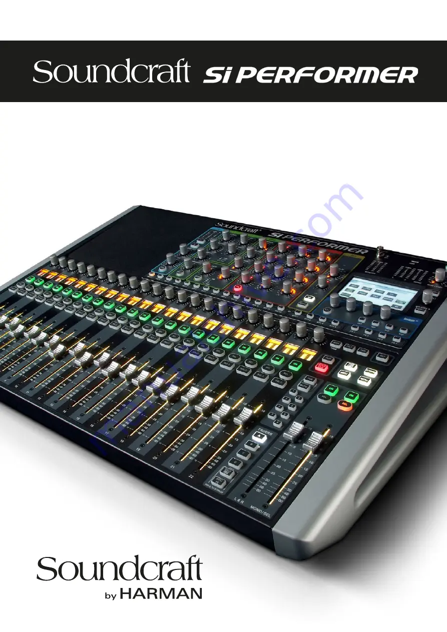
®
User Guide
v2.0
For Soundcraft Si Performer 1, 2 & 3
Incorporating Software version 1.6
Page 1: ...User Guide v2 0 For Soundcraft Si Performer 1 2 3 Incorporating Software version 1 6...
Page 2: ...quipment does cause harmful interference to radio or television reception which can be determined by turning the equipment off and on the user is encouraged to try to correct the interference by one o...
Page 3: ...ses 7 0 DSP Elements 7 1 Function Focus 7 2 ACS Channel Strip Elements 7 2 1 ACS Input 7 2 2 ACS Gate 7 2 3 ACS Compressor 7 2 4 ACS Equaliser 7 2 5 ACS Output 7 3 Control Channel 7 4 Graphic EQ GEQ 8...
Page 4: ...annels to mix 64 Mono input channels 8 Stereo input channels Soundcraft 4 band British EQ on all inputs and outputs Soundcraft Dynamics available on all channels Delay available on all channels BSS Gr...
Page 5: ...d with the letter L Ensure that these colour codings are followed carefully in the event of the plug being changed This unit is capable of operating over a range of mains voltages as marked on the rea...
Page 6: ...ing is required when the apparatus has been damaged in any way such as power supply cord or plug is damaged liquid has been spilled or objects have fallen into the apparatus the apparatus has been exp...
Page 7: ...ich your console arrived forms part of the product and must be retained for future use NOTE This equipment has been tested and found to comply with the limits for a Class A digital device pursuant to...
Page 8: ...the End User whilst in transit both to and from the Dealer or Soundcraft and postage must be prepaid 4 This warranty shall only be available if a The Equipment has been properly installed in accordan...
Page 9: ...elay 1sample 500ms GEQ 31Hz 16kHz 1 3 octave GEQ 31Hz 16KHz 1 3 octave Digital I O AES Sample rate converter range 8kHz 200kHz External Word Clock In range 48kHz 7Hz internal systems 3Hz with stagebox...
Page 10: ...would be the feature list on the introductory page chapter reference 1 0 which will familiarise you with all of the main possibilities facilities and functions Please note Most of the illustrations i...
Page 11: ...be controlled by any Control Channel these elements are considered separate in this manual Section 5 deals with the console s patching system which connects physical inputs and outputs to DSP chan nel...
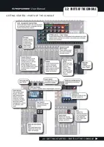
Page 12: ...User Manual 2 2 PARTS OF THE CONSOLE GETTING STARTED PARTS OF THE CONSOLE 2 2 GETTING STARTED PARTS OF THE CONSOLE...
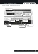
Page 13: ...User Manual 2 2 PARTS OF THE CONSOLE GETTING STARTED PARTS OF THE CONSOLE 2 2 GETTING STARTED PARTS OF THE CONSOLE...
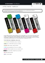
Page 14: ...The main principle of FaderGlow is to indicate the current fader function with colour so more immediate recognition is possible Soundcraft FaderGlow is fitted to all console faders that can change th...
Page 15: ...ntrol Channels These are the vertical strips containing a Fader Encoder Status Meter screen plus the SOLO SEL and ON switches They are assigned to control real input and output channels as well as GEQ...
Page 16: ...plus the Left Right and Mono Centre main mix Control Channels By default Layers A and B are assigned to input channels with the Stereo input channels on the right hand end of layer B Layer C is assign...
Page 17: ...der indicators plus ON SOLO and SEL buttons The SEL button is used to focus the Assignable Channel Strip ACS on that channel The DSP channel controlled by a Control Channel is determined by the curren...
Page 18: ...annel though the Assignment menu parameters are exclusive you cannot assign more than one function to a Control Channel Fader Bank Shows the currently selected Fader Layer This parameter cannot be edi...
Page 19: ...Master Channel to the currently selected Control Channel Touching the value field will bring up a scrollable list of available DMX Masters 1 4 Assign Mixes Assign a MIX Master channel to the currently...
Page 20: ...NSERT BLANK right for example will push all Control Channels to the right of the currently selected slot one slot to the right The rightmost control channel will be lost You will be asked to confirm t...
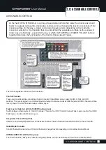
Page 21: ...Encoders The encoders at the tops of the control channels can be switched globally between three different functions GAIN TRIM FILT HPF adjust and PAN simply by pressing the corresponding Global Enco...
Page 22: ...you can control all input EQ dynamics and output functions available to the selected channel Adjusting an ACS control will trigger the Function Focus feature and the console Touch Screen will reflect...
Page 23: ...n pressing the MIX 1 Fader Follow button will assign all channel faders to control the Mix 1 sends for those channels and the Mono control channel fader to control of the Mix 1 Master This allows one...
Page 24: ...y as well as settings for inputs outputs monitoring the solo system plus a frequency response type display of the 4 band EQ MENU Access the Touch Screen Main Menu Encoder Scroll or adjust parameters a...
Page 25: ...w load reset functions for show files Isolate settings are used to isolate parameters from show recalls See section 9 1 Show Storage and recall for more detail The RESET CONFIG function forces the con...
Page 26: ...tup and patching of the four available insert sends and returns See section 5 Inputs Outputs For more information Remember an insert interrupts signal flow so if an insert is assigned to a channel the...
Page 27: ...ons See section 13 for more detail OUTPUTS DMX Output channel or DMX specific settings The menu will change depending on whether an Output channel Mix Bus Master Matrix Master LR or M C Main or a DMX...
Page 28: ...ich is used whenever the console is reset to its default SYSTEM menu RESET PATCHING or RESET ALL Additionally the console has two ViSi compatible option card slots one with 64 in 64 out expan sion cap...
Page 29: ...l ST 01 shows LINE IN1 in the Input Patch menu item then the left channel will be patched to LINE IN1 and the right channel will be patched to LINE IN2 In the patching screen both LINE IN 1 and LINE I...
Page 30: ...p in the INSERT menu Use the INSERT ASSIGN menu to assign insert points to channels and use the INSERT SETUP button on the same screen to assign insert sends and returns to physical outputs NOTE Patch...
Page 31: ...l device setup is saved in show files and Mic Gain and 48V values can be recalled with snapshots Snapshot recall of these values can also be disabled with the ISOLATE feature Network Settings The firs...
Page 32: ...ut Channel and the last set gain value Node Address Set the Soundweb London devices node address to send and receive HiQnet values to your Si console The node address can be found and adjusted in Lond...
Page 33: ...11 14 Si Performer 2 Mic In 1 22 Channels 1 22 Fader Layer A slots 1 22 Mic In 23 24 Channels 23 24 Fader Layer B slots 1 2 Unassigned inputs x 12 Channels 25 38 Fader Layer B slots 3 14 Line Inputs...
Page 34: ...wide range of ViSi I O cards or a Soundcraft Stagebox with MADI card installed There are a variety of available ViSi modules including a MADI card that an be used to add a Soundcraft Stagebox for exp...
Page 35: ...ual Port CAT5 MADI redundant link Dual Port Multi Mode SC Optical MADI redundant link AES 3 XLR 4ch in 4ch out on XLRs AES D Type 8ch in 8ch out 25 way D SUB connector Multi Digital Card 32 in 32 out...
Page 36: ...NPUTS OUTPUTS ViSi CONNECT CARDS BLU Link 32 x 32 interface to Soundweb London digital audio bus Aviom A Net 16 output channels CAT5 Pro 16 head CobraNet Up to 32 in and 32 out MADI USB 32 in out MADI...
Page 37: ...Si Series and Vi Series consoles via a MADI card fitted to the option card slot Soundcraft Compact Stagebox A high density of I O connections in only 4U of rack space The modular unit is fully config...
Page 38: ...eral basic channels and busses These are mono and stereo input channels mono and stereo Mix Busses and MIX output master channels MIX 1 14 internal FX send mix busses FX 1 4 stereo Matrix mix busses a...
Page 39: ...to any or all of the MIX 1 14 Mix busses which feed the Mix Bus Master channels the Main L R and Mono Centre mix busses or to the FX send busses which get routed to the internal Lexicon FX The levels...
Page 40: ...User Manual 6 1 INPUT CHANNELS CHANNELS BUSSES INPUT CHANNELS 6 1 CHANNELS BUSSES INPUT CHANNELS...
Page 41: ...is channel will not be affected and its setting will not be changed However current channel settings are still stored when a cue is stored Please note To prevent conflict Isolation function does not i...
Page 42: ...in LCR mode is active to increase decrease the contributions to the LR and Mono buses when panning DirectOut Patch Choose an analogue or digital output for this channel s Direct Output Touching the v...
Page 43: ...channels via the Fader Layers FADERS button group or by selecting the bus mix via the tOTEM FADER FOLLOW buttons The Fader Layer C is the default layer for the Mix Masters though remember that contro...
Page 44: ...User Manual 6 2 MIX OUTPUTS CHANNELS BUSSES MIX OUTPUTS 6 2 CHANNELS BUSSES MIX OUTPUTS...
Page 45: ...stored Mix Width Select Mono or Stereo width for this Mix Bus Note only Mix busses 7 14 can be switched to stereo Mix busses 1 8 are mono only There are various Mix Output specific options found via t...
Page 46: ...ouch Screen Two outputs can be allocated with individually patchable left and right connections For more detail please see section 5 Inputs Outputs Pre Fader Source Select which Pre Fader tap source i...
Page 47: ...sses and masters are stereo and the Matrix Master channels have two patchable stereo outputs each Left and Right of both outputs are interdependently patchable All Matrix channels include a Graphic Eq...
Page 48: ...User Manual 6 3 MATRIX OUTPUTS CHANNELS BUSSES MATRIX OUTPUTS 6 3 CHANNELS BUSSES MATRIX OUTPUTS...
Page 49: ...be changed However current channel settings are still stored when a cue is stored Matrix Width Choose Mono or Stereo type for the Matrix Master Output Patching Choose specific analogue or digital outp...
Page 50: ...reo output channel which is permanently assigned to the Left Right Control Channel The Mono bus feeds the main Mono Centre output channel which during normal operation is controlled by the MONO SEL co...
Page 51: ...ll not be changed However current channel settings are still stored when a cue is stored Patching Choose specific analogue and digital outputs for this DSP Channel Touching the value fields will bring...
Page 52: ...xclusively to feed the internal Lexicon FX units They receive input from the Input Channels Those contributions are accessed via the FX 1 4 tOTEM FADER FOLLOW buttons Management of the Lexicon FX is d...
Page 53: ...common DSP processing elements and controls via the Control Channel and Assignable Control Section ACS This chapter explains those elements and their controls Please note some elements will not be ava...
Page 54: ...ou are currently adjusting and any other controls in its group plus the channel name and alternate units for the same control For example DELAY is illustrated in ms milliseconds feet and meters while...
Page 55: ...to that It is broken down in to small colour coded sections making it easy to identify control groups and functions at a glance There is a dedicated control for each function and each control has a d...
Page 56: ...graph The scale is relative to digital full scale so 0dBfs is the maximum before clipping For input channels the meter source is PRE just after the analogue to digital conversion but before the rest o...
Page 57: ...ust before the cut off frequency Use it to filter out low frequency rumble and clean up live microphone feeds for example GAIN TRIM Adjust mic gain or line trim for input channels The control changes...
Page 58: ...in input voice instrument etc is silent This gate includes a Sidechain Filter section This allows you to control what frequency range is compared to the threshold level For instance you could limit th...
Page 59: ...S C HPF Adjust the Sidechain High Pass Filter This filter cuts out low frequencies Gate Status LEDs Indicate the current operating status of the gate OPEN inactive the gate is passing signal and audi...
Page 60: ...g the peak level or to control overly dynamic sources ATTACK Adjust the Attack time of the Compressor The time it takes for the compression function to reach full attenuation after the threshold has b...
Page 61: ...10dB above threshold comes in it will be attenuated to 5dB 5dB above threshold which is 10dB divided by 2 In the same instance if the ratio was 5 1 then the signal would be attenuated to 8dB which is...
Page 62: ...he filter will boost or cut the signal at this frequency by the amount set by HF Level The cut off frequency will be lower according to the filter slope HF Q Adjust the Q of the HF filter and switch b...
Page 63: ...the Touch Screen with the Function Focus feature HI MID FREQ Adjust the centre frequency of the HI MID filter Frequencies above and below this within the bounds of the Q setting will be affected by th...
Page 64: ...fectively sets the width bandwidth of the filter s bell shape and FREQ sets the frequency at the centre of the bell shape LF Level Adjust the boost attenuation of the LF bell filter EQ On Off Switch t...
Page 65: ...djust the delay applied to this DSP Channel ACS units are milliseconds though the Touch Screen will show feet and meters as well with the Function Focus feature PAN Adjust the Pan or balance for stere...
Page 66: ...e Main Left Right Stereo Bus Any channels routed to LR will be summed into the Main LR Master Output Channel controlled by the L R Control Channel M Main Mono Centre Bus Routing Route the selected cha...
Page 67: ...lobal Encoder Mode selection GAIN Encoders function as the input GAIN or TRIM for line digital sources for all the channels on the currently active fader layer No function in for Mix Bus or Matrix mas...
Page 68: ...Meter Indicates audio level for the selected channel dBfs ON ON key function is dependant on the channel type and selected fader layer Momentary Latch ing behaviour available from software version 1...
Page 69: ...X controllers 1 14 for Performer 1 1 22 for performer 2 and 1 30 for per former 3 to create four presets that work on a highest value precedence per controller See section 13 for more detail The conso...
Page 70: ...en any output channel is selected the GEQ LO and GEQ HI buttons FADERS button group will assign 14 bands to the Control Channel Faders colour coded with red FaderGlow Faders are centre 0dB posi tion d...
Page 71: ...have any effect GEQ LO Press to assign the 14 low GEQ bands 31Hz 630Hz to the Control Channel Faders An output channel Mix Bus Matrix Bus LR Mono bus masters must be selected for this button to have...
Page 72: ...eate up to eight VCA Groups using the VCA SETUP button and the Mute VCA group Master buttons 1 8 8 3 Copy Paste Copy then Paste whole channels channel sections FX settings and Mix bus FX send and Matr...
Page 73: ...r hold Interrogate Mute Groups This mode allows you to configure Mute Group assignments in conjunction with the Mute Group Masters buttons 1 8 The button illuminates Red when active To Interrogate Mut...
Page 74: ...lected Mute Group CLR Clear Selection While in Mute Group Setup mode holding the CLR button and pressing a Mute Group Master button will clear that Mute Group ALT CLR Clear all While in Mute Group Set...
Page 75: ...r example you could put the whole durm kit under the control of a single VCA Master or if you have a multiple mics on a guitar cabinet you could set the ratios with individual channels and then create...
Page 76: ...ter fader works as an offset to the current channel faders does not move the meme ber faders so it s a good idea to set group members and the Master to nominal levels When assigned VCA Master Faders s...
Page 77: ...tus indication Red illuminated ON buttons indicate a channel that has either been muted by a VCA Master or a Mute Group Master Green ON buttons indicate an active un muted channel and an unlit ON butt...
Page 78: ...the state of that selection If you have a channel selected that channel s processing except GAIN or 48V status is copied if you have a bus mix selected via the FADER FOL LOW tOTEM buttons that bus mix...
Page 79: ...utton selected you can use COPY PASTE mode to copy and paste an entire MIX MTX or FX Bus Mix For example you could copy the MIX 1 contribution levels from all Input Channels and paste those levels as...
Page 80: ...els the current Fader Layer must include input channels 2 Press and hold the ACS button for the chosen function HPF GATE EQ LR and so on The SEL Select buttons of any channels where that function is a...
Page 81: ...input channels or any output channel are soloed then AFL routing will be used You can also set the Input Solo Mode as PFL only or AFL only Highlight and Blend settings in the Solo Settings menu allow...
Page 82: ...atus Indicators Indicators light to show Solo mode status If only a single input channel is soloed then PFL routing will be used If two or more input channels or any output channel are soloed then AFL...
Page 83: ...is control is independent of the main monitor level control Input Solo Mode Set the Input Solo Mode to Auto AFL or PFL In Auto Mode the console chooses Pre fade Listen solo PFL when only one Input Cha...
Page 84: ...e headphones output located below the front of the console near fader 1 with level controlled by the MON LEVEL encoder There is also a parallel Monitor Output Patch available allowing the engineer to...
Page 85: ...w Mono Check Outputs a mono sum of the stereo monitor signal This adds left and right monitor outputs together A mono check is important when compatibility with mono play back devices is required some...
Page 86: ...eters channels and bus mixes across the whole of the console CLR Functions CLR SEL button Channels Reset all audio parameters within the channel or bus to the factory defaults does not affect function...
Page 87: ...e selected VCA Master ALT CLR Functions ALT CLR SEL Reset all audio parameters in all like for like channels across the whole console does not affect functions such as SOLO bus type names patching and...
Page 88: ...TX 1 14 Resets all channels contributions to all four Matrix busses to zero It Does not affect the Matrix bus master channels or master levels ALT CLR Any Mute Master Button While in MUTE setup mode C...
Page 89: ...NAPSHOTS The console file system uses the Show as it s basic file The Show contains all console settings plus the Cuelist The Cuelist contains recallable Cues that contain Snapshots of console setting...
Page 90: ...om console automation snapshot recall rather than Show loading NEW SHOW Create a new Show A new show deletes all cues and their associated events but retains names audio settings patches and similar s...
Page 91: ...a re discovery of any installed option cards or connected I O system such as a Soundcraft Stagebox The system will provide a warning that the action will overwrite the current configuration database...
Page 92: ...will recall a the snap shot and HiQnet Transmit send a HiQnet venue preset event When you store a cue you also take a snapshot to be stored with that cue The console s Cuelist is a list of cues that c...
Page 93: ...st The Snapshot will be added to the end of the Cuelist and named automatically Unnamed Snapshot n where n is the snapshot s numbered position in the Cuelist Remember that the number in the snapshot n...
Page 94: ...2 1 for more detail MOVE UP Move the currently highlighted Cue up one in the Cue List This action affects the currently highlighted Cue which is not necessarily the currently active Cue Up means to t...
Page 95: ...smit active in the Cue DMX Status Highlighted yellow to indicate there is a DMX lighting component to this cue You can prevent DMX changes in a cue by selecting Audio Only Cue Type in the EDIT CUE men...
Page 96: ...can transmit MIDI program changes when they are recalled HiQnet is a network protocol developed by Harman Pro for communications and control between audio system components The console can send HiQne...
Page 97: ...d named automatically Unnamed Snapshot n where n is the snapshot s numbered position MIDI Program Number Choose a MIDI Program Change number MIDI Channel Choose a MIDI channel for the specified Progra...
Page 98: ...Venue preset when the Cue is recalled Console network settings including IP settings and HiQnet Enable and Address options can be found in the Touch Screen SYSTEM menu reference chapter 11 HiQnet Venu...
Page 99: ...selected bus to its fader The Stereo Return channel is as signed to the MONO SEL Control Channel on the right hand end of the console Return Routing The Stereo Input channels ST 5 ST 8 are by default...
Page 100: ...in COPY PASTE mode select processors for Copy Paste function ADJUST SCROLL Touch Screen Control Can be used instead of touch to select an FX processor FX Encoders Adjust the corresponding FX paramete...
Page 101: ...sients like a voice Drum Hall has a higher diffusion setting which is necessary to smooth out faster transient signals found in drums and percussion instruments In addition to general instrumental and...
Page 102: ...a micro phone connected by a simple set of springs The characteristic boing of a spring is an important component of many classic rock and rockabilly guitar sounds Reverse Reverb Reverse reverb works...
Page 103: ...ettings shorten reverb times and should be used when a smaller apparent space or a more subtle effect is desired ER Level Early Reflections Level Adjust the level of early reflections within the rever...
Page 104: ...e large flat walls cause low diffusion For drums and percussion try using higher Diffusion settings Bass Bst Bass Boost Boost or cut frequencies below the Bass Boost Frequency the transition point fro...
Page 105: ...by an LFO low frequency oscillator that produces a chorusing effect on the delay repeats This is a great delay for guitar and instrument passages that need that special something Mono Delay The Mono...
Page 106: ...and Pong Delay Hi Pass Frequencies below this are filtered removed Lo Pass Frequencies above this are filtered removed Duck Lvl Duck Level Set the input signal level at which ducking occurs Studio Mo...
Page 107: ...ffect this controls the delay time offset between left and right taps expressed as a ratio of left to right time difference In the centre the taps have the same time 1 1 Swap Tap Swap Swaps the delay...
Page 108: ...s an AutoPanner effect is generat ed with the amplitude of one channel being raised whilst that of the other channel is lowered Vibrato Vibrato is obtained by smoothly varying the pitch of the signal...
Page 109: ...r of additional Chorus voices Higher amounts add more richness to the Chorus effect Regeneration Controls the amount of modulated signal being fed back into the input creating feedback Higher amounts...
Page 110: ...This control affects the output of the LFO only It has no effect on the outputs of the individual waveforms Phs Stgs Phase Stages Selects between a 4 8 or 12 state phase shifter Spread Stereo Spread I...
Page 111: ...speed limits are used when the speed parameter is changed from Slow to Fast Doppler Increases or decreases the Doppler pitch effect The Doppler effect is a rise and fall in pitch experienced by an ob...
Page 112: ...For creating cascading arpeggio type effects Pan n Sets the pan position in the stereo field for each tap in the 2 Tap Delay or each channel of the pitch shift detune effects Allows the stereo width t...
Page 113: ...at mix pre amps don t affect the Direct Outputs levels 11 2 SYSTEM The System menu provides information about the console itself as well as offering settings for the console name date time wordclock a...
Page 114: ...ystem enable LED Brightness Adjust the brightness of LEDs across the console This includes all Encoder level indicators metering and status LEDs FaderGlow Brightness Adjust the FaderGlow brightness ac...
Page 115: ...Direct Out Gain Stabiliser system D O G S is a tool that prevents Direct Output levels from changing when a Mic Gain is changed so any feeds taken from the console remain stable That is it maintains s...
Page 116: ...CHANNELS Reset all Input audio channels to factory default Includes all Input Channel audio parameters channel name and channel type Mono Linked It does not include patching You will be asked to confi...
Page 117: ...ou will be asked to confirm this action in the Touch Screen Software Version Current software version Read only EVENT LOG A log of specific system events Can be useful for trouble shooting and for tec...
Page 118: ...e effect Wordclock Choose an Internal External or Option card wordclock reference The console can be set as Word Clock Slave EXTernal or OPTION or Master INTernal When set to EXTernal the console will...
Page 119: ...ility On of Off This console can transmit HiQnet Venue Events on the network along with cue recalls Please see chapter ref erence 9 2 for more detail The console can also control Soundweb London Devic...
Page 120: ...when they are created Editing of users and profiles is only available when logged on as the administrator Please note Passwords cannot be easily recovered if lost or forgotten The factory default Admi...
Page 121: ...easily recovered if lost or forgotten DELETE USER Delete the selected User The system will ask for confirmation in the Touch Screen to confirm this action User Select Select A User from the current li...
Page 122: ...apter reference 11 3 2 for more detail User Name Name the User Touching or selecting the value field brings up a QWERTY keyboard in the Touch Screen Profile Profile Name Use the Profiles Menu to add a...
Page 123: ...1 3 1 ADD EDIT USER SYSTEM SETTINGS SECURITY ADD EDIT USER 11 3 1 SYSTEM SETTINGS SECURITY ADD EDIT USER CANCEL Cancel the current User creation or edit without saving any altered values SAVE Save the...
Page 124: ...utput On Faders GEQ Fader Layer A Fader Layer B Fader Layer C Fader Layer D FX Touch Screen and Cue List NOTE If a Cue recall will change an aspect of console functionality that is locked but Cue List...
Page 125: ...CURITY PROFILES CANCEL Cancel the current Profile creation or edit without saving any altered values SAVE Save the current Profile Profile Select a profile to view or edit Touch or select the value fi...
Page 126: ...sing the Power key Press and hold Power Key until it flashes orange then press it again 3 Press and hold the Power key for approx 5 seconds A Software Loader screen shall appear 4 Insert the USB stick...
Page 127: ...se the RESET options in the SYSTEM menu to set parameters and settings back to factory default without destroying data Remember All settings cues users profiles and shows will be lost 1 Starting with...
Page 128: ...to route directly to the console s LR and MONO buses though you can route the Oscillator signal to a Mix bus master then use the LR and MONO routing keys Oscillator patching is stored in Snapshots Os...
Page 129: ...e Set the signal type for the Oscillator output Either Sine Wave or Pink Noise Full spectrum equal power per octave Oscillator Out Patch Set a physical output for the Oscillator signal Touching or sel...
Page 130: ...g console It has four layers ALT FADERS A D of identical DMX channel faders and each layer has its own DMX Master fader MONO SEL fader A D DMX Fader Layers are accessed by presing and holding the ALT...
Page 131: ...asters A D Si Performer 2 has 22 faders on each layer 4 x 1 22 hard patched to DMX channels 1 22 plus a Master Fader for each Layer DMX Masters A D Si Performer 3 has 30 faders on each layer 4 x 1 30...
Page 132: ...Master Control Channel with its SEL button You can then use the Touch Screen OUTPUTS DMX Menu to rename the selected Channel or Master FADE TIME CUELIST EDIT CUE Set a Dimmer Fade Time for DMX Cue tra...
Page 133: ...sted at 5 2 You can check which Control Channel is controlling which Input Channel in the FADER SETUP menu See 3 2 1 You can check which physical input is patched to an Input Channel by selecting the...
Page 134: ...d patches and that the signal is being returned from an external processor for example Reference section 5 1 has specific information on Insert patching Is the Channel on and unmuted If a Control Chan...
Page 135: ...ster Channel Path valid Almost exactly the same checks as above can be done on the Output Master Channel whether it s a MIX MATRIX or LR M Master For detailed path troubleshooting check the signal pat...