background image

Harman®  •  P-Series Owner’s Manual_R23  •  2014 - ___  •  02/19

17

3-90-436168c

Whenever adding fuel, take the opportunity to clean the burn 

pot. 

(Weekly at minimum)

•   Scrape the top holed surface and sides of the burn pot 

down to auger tube Figure 5.1. It is not necessary to 

completely remove all material from the burn pot. The 

excess will be pushed out during the next use.

•  With  the  fire  out  and  burn  pot  cold,  use  the  supplied 

allen wrench to remove any build-up that may have 

accumulated in the holes of the burn pot grate. Simply 

push the allen wrench down through each hole ensuring 

it is clear of any build-up paying attention not to damage 

the igniter element in the process. 

Monthly, or after each ton of fuel burned:

•  Loosen the (2) wing thumb screws on the lower front angle 

of the burn pot. Figure 5.2

•  Lift off the clean-out cover to open the bottom clean-out 

chamber. Figure 5.3

•  Clean ash buildup from inside the chamber while cover 

is off. Use the scraper to tap on the top front edge of the 

burn pot. This will help knock pieces of ash, loosened 

by the scraping process, down through the holes. It also 

helps knock scale off of the igniter element.

Figure 5.3

The igniter is made to be removable for service by insulated 

male/female wire connectors. These connections between 

the hot leads (the wires inside the burn pot) and the cold 

leads (the wires from the control board) are always pulled 

to the inside rear of the feeder body.

 (Not coiled inside the 

burn pot.)

It is very important that these connections are to the inside 

rear of the feeder body. Also, the extra wire of the igniter wire 

service loop must be pulled out through the rear of the feeder 

and tied up so that it will not be damaged by any moving parts. 

Note: The hot lead/cold lead connection must always 

be pulled to the rear of the feeder body before 

operation.

E. Burnpot Maintenance

Figure 5.1

Figure 5.2

Wing Thumb Screws

Figure 5.3

 - Viewed from below through the ash 

pan opening.

Igniter hot lead wires

(High temperature)

Burn pot igniter

Use caution when cleaning burn pot clean-out 

chamber. Do not damage the high temperature igniter 

wires.

WARNING

!

Disconnect the power to the unit before removing 

cover.

DANGER

!

Summary of Contents for P43

Page 1: ...s Keep children away CAREFULLY SUPERVISE children in same room as stove Alertchildrenandadultstohazardsofhightemperatures High temperatures may ignite clothing or other flammable materials Keep clothi...

Page 2: ...et le manuel du propri taire Remplacer le verre seulement avec 5mm miroir en c ramique disponibles chez votre revendeur Ne ENLEVEZ PAS CETTE TIQUETTE NE PAS CETTE TIQUETTE enlever MODEL MOD LE P61A Ro...

Page 3: ...anual Ignition 24 E Service Parts 25 P43 25 P61A 29 P68 34 F Limited Lifetime Warranty 40 G Contact Information 44 Contains updated information 1 Welcome A Congratulations 2 2 Product Specific and Imp...

Page 4: ...Use STANDARD s ASTM E 1509 04 ULC ORD C1482 M1990 ULC S627 00 EPA Method 28 5G MODEL P61A Pellet Stove LABORATORY OMNI Test Laboratories Inc REPORT NO 135 S 22 4 135 S 22b 6 2 TYPE Pellet Fueled Suppl...

Page 5: ...ency using data collected during EPA emissions test Weighted average HHV efficiency using data collected during EPA emissions test A range of BTU outputs based on EPA Default Efficiency and the burn r...

Page 6: ...Safety 3 General Information B Clear Space WARNING RISK OF FIRE Do NOT place combustible objects in front or to the sides of the appliance High temperatures may ignite clothing furniture or draperies...

Page 7: ...r scale marked from 1 to 7 Mode Selector Allows you to choose between Room Temp Mode Constant burn Mode or OFF Also allows you to vary the distribution blower speed by turning the knob to the high or...

Page 8: ...od by products Source material typically determines ash content Higher Ash Content Material Hardwoods with high mineral content Bark and leaves as source material Standard grade pellets Lower Ash Cont...

Page 9: ...ally set If the appliance is set at one of the lower settings it will run quieter but take longer to heat up an area than if it were set at a higher burn rate Regardless of the burn rate when the area...

Page 10: ...stics test to insure the control is operating properly This is normal 3 For your first fire it may be necessary to purge the auger system by putting the feed limit knob to Test prior to starting the u...

Page 11: ...emp mode however the blower will turn on and off in accordance to what temperature the room sensor is reading When the room sensor is satisfied the blower will shut down until the room sensor sees a d...

Page 12: ...r element to operate if the view door is open 4 Adjust Feed Limit If this is your first fire or you are trying different pellets set the feed limit to 4 Figure 4 6 This is a conservative number and wi...

Page 13: ...tant fuel consumption rate is sacrificed for exact room temperature Therefore as it gets colder more pellets will be burned automatically The distribution blower speed will vary according to the posit...

Page 14: ...ce before servicing Smoke spillage into room can occur if appliance is not cool before unplugging Risk of shock if appliance not unplugged before servicing appliance CAUTION When properly maintained y...

Page 15: ...ashes into a steel non combustible container with tight fitting lid outside Use provided paint brush Vacuum loose ash from around igniter and inside burn pot Stove MUST be turned off cold and unplugge...

Page 16: ...e self adhesive 1 4 gasket material around the front face of the glass Set the glass panel and gasket gently onto the door Install the hold down clips and tighten with bolts Glass Cleaning Sometimes i...

Page 17: ...e burn pot This will help knock pieces of ash loosened by the scraping process down through the holes It also helps knock scale off of the igniter element Figure 5 3 The igniter is made to be removabl...

Page 18: ...ke cover pull towards the front of the unit while sliding to the right Figure 5 6 Now that the combustion intake cover is removed you can remove any flyash or debris that has collected around combusti...

Page 19: ...16 wing nut Figure 5 8 Lift up and slide the cover off of the threaded stud Inspect and clean the inner chamber if necessary Figure 5 9 Reinstall the cover making certain it is seated properly on the...

Page 20: ...et disconnect power cord for a few seconds and reconnect If error still occurs call your Dealer A Error Code Description B Frequently Asked Questions ISSUES SOLUTIONS 1 Metallic noise 1 Noise is cause...

Page 21: ...osis of a problem and the corrective action to be taken This troubleshooting guide can only be used by a qualified service technician STOVE DOES NOT FEED 1 No fuel in hopper 2 Firebox draft may be too...

Page 22: ...iner until all cinders have thoroughly cooled Soot and fly ash Formation and need for removal The products of combustion contain small particles of fly ash The fly ash will collect in the exhaust vent...

Page 23: ...ty control There are 2 high limits one normal operation high limit and one backup high limit The control has an automatic diagnostic circuit that continuously monitors the ESP and Room Sensor for faul...

Page 24: ...emain shut down If the fire is out and the ESP is still warm the feeder may restart Since the fire is out the ESP temperature will not rise The unit will then shut down and may flash a six blink statu...

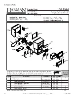
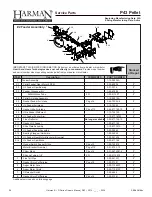
Page 25: ...1 10 04300 Y Hopper Knob Post 008168147 1 00 02000 1 Hopper Latch Assembly Post 008168147 1 00 773901 Hopper Lid w Hinge Swell Latch Pre 008168147 1 10 08518 Hopper Lid w Hinge Knob Post 008168147 1...

Page 26: ...Gasket Ultra Air Intake Pkg of 10 3 44 677160 10 Y 2 8 Ultra Feeder Weldment 1 10 724132 Y 2 9 UL Feeder Pusher Arm 1 10 677187W Y 2 10 Fines De ector No longer available 2 00 677138 10 2 11 Gasket U...

Page 27: ...7738106A Post 008168147 1 10 773904A Wood Handle Pre HF183104 3 40 08746 3 Post HF183104 1600663 Y 17 Bolt on Hinge 2 00 06968B 18 Cast Door Frame 4 00 06800P Cast Door w Glass 1 10 06800A 19 Glass P...

Page 28: ...et Hopper Throat 3 44 677185 Y Gasket Burn Pot 3 44 237639 Y Glass Clip Pkg of 4 1 00 249140 Y Hopper Muf er and Fitting 1 set 1 00 18186618 Y Igniter 3 20 677200 Y Pkg of 10 1 00 677200 Y Label Cauti...

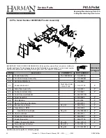
Page 29: ...n COMMENTS PART NUMBER 1 Hopper Assembly Pre 008085092 1 10 08622 Y Post 008085092 1 10 05803 Hopper Extension Switch Kit 1 00 06826 Y Hopper Knob Post 008093438 1 00 02000 1 Hopper Latch Assembly Pos...

Page 30: ...61 2 3 Feeder Weldment Must Also Order 1 00 677122 1 10 677150 Y 2 4 Slide Plate Assembly 1 10 08037 Y 2 5 Pusher Arm Assembly 1 10 06691 Y 2 6 Feed Cover and Gasket 2 00 247217B 2 7 Auger Assembly 3...

Page 31: ...r Air Intake Pkg of 6 3 44 72224 6 Y 3 6 UL Feeder Air Intake 1 10 72228 3 7 Gasket Ultra Air Intake Pkg of 10 3 44 677160 10 Y 3 8 Ultra Feeder Weldment 1 10 724132 Y 3 9 UL Feeder Pusher Arm 1 10 67...

Page 32: ...Y 13 Rear Cover Right 2 00 06468 2P Y 14 Comb Intake Weldment 1 10 08516S Y 15 Retainer Assembly 1 10 08533S Y 16 Ash Pan 1 10 05800 Y 17 Ash Door Assembly Pre 008093438 1 10 06724S Post 008093438 1 1...

Page 33: ...Tailpipe Pkg of 5 1 00 07381 Y Gasket Hopper Lid 1 00 00248 Y Hopper Lid W Hinge Swell Latch Pre 008093438 1 10 09109 Y Hopper Lid w Hinge Knob Post 008093438 1 10 06493 Igniter 3 20 677200 Y Pkg of 1...

Page 34: ...688 12 Forest Green Jan 2010 Retired Units IMPORTANT THIS IS DATED INFORMATION Parts must be ordered from a dealer or distributor Hearth and Home Technologies does not sell directly to consumers Provi...

Page 35: ...1 2 3 Feeder Weldment Must Also Order 1 00 677122 1 10 677150 Y 2 4 Slide Plate Assembly 1 10 08037 Y 2 5 Pusher Arm Assembly 1 10 06719 Y 2 6 Feed Cover and Gasket 2 00 247217B 2 7 Auger Assembly 3 5...

Page 36: ...embly 1 10 06810A 3 5 Gasket Feeder Air Intake Pkg of 6 3 44 72224 6 Y 3 6 UL Feeder Air Intake 1 10 72228 3 7 Gasket Ultra Air Intake Pkg of 10 3 44 677160 10 Y 3 8 Ultra Feeder Weldment 1 10 724132...

Page 37: ...r Left 2 00 06468 1P Y 13 Rear Cover Right 2 00 06468 2P Y 14 Door Latch Assembly 1 00 06713 Y Contains Latch Adjustment SHCS 1 4 20 X 1 Lock Nut 1 4 X 20 Jam Nut HX Jam 1 4 20Z Steel Bushing 15 Comb...

Page 38: ...0637 Y Draft Meter Bolt and Tube 1 00 04004 Fuse 5 Amp Pkg of 5 3 20 23705 5 Y Gasket 1 4 Rope Black W PSA Glass 15 Ft 1 00 2312 Y Gasket 3 8 Rope White LD Ash or Load Door 30 Ft 1 00 00888 Y Gasket B...

Page 39: ...and serial number when requesting service parts from your dealer or distributor Stocked at Depot ITEM Description COMMENTS PART NUMBER Leaf Door Trim Gold 3 43 06717 4 Brushed Stainless 3 43 06717 7 B...

Page 40: ...ing or six months after the sale of the product by an independent authorized HHT dealer distributor whichever occurs earlier However the warranty shall commence no later than 24 months following the d...

Page 41: ...e changes in color of interior and exterior surface finishes may occur This is not a flaw and is not covered under warranty Damage to printed plated or enameled surfaces caused by fingerprints acciden...

Page 42: ...t limited to improper chimney or venting installation LIMITATIONS OF LIABILITY The owner s exclusive remedy and HHT s sole obligation under this warranty under any other warranty express or implied or...

Page 43: ...Harman P Series Owner s Manual_R23 2014 ___ 02 19 43 3 90 436168c...

Page 44: ...___________________________________________________________________________ ________________________________________________________________________________ ___________________________________________...

Reviews: