AVR 520
Audio/Video Receiver
OWNER’S MANUAL
®
Power for the Digital Revolution.
Page 1: ...AVR 520 Audio VideoReceiver OWNER S MANUAL Power for the Digital Revolution ...
Page 2: ...ry 37 Auto Search Method 37 Code Readout 37 Learning Codes 38 Erasing Learned Codes 38 Macro Programming 39 Programmed Device Functions 40 Volume Punch Through 40 Channel Control Punch Through 41 Reassigning Device Control Selectors 42 Function List 44 Setup Code Tables 54 Troubleshooting Guide 54 Processor Reset 55 Technical Specifications AVR 520 Audio VideoReceiver Typographical Conventions In ...
Page 3: ...layers the AVR 520 also features wide bandwidth low crosstalk component video switching Coax and optical digital outputs are available for direct connection to digital recorders and both the front panel analog audio video and coaxial digital jacks may be switched to outputs for use with portable recorders a Harman Kardon exclusive Two video recording outputs preamp out and main amp in jacks and a ...
Page 4: ...is exposed to direct sunlight or heating equipment Avoid moist or humid locations Do not obstruct the ventilation slots on the top of the unit or place objects directly over them Cleaning When the unit gets dirty wipe it with a clean soft dry cloth If necessary wipe it with a soft cloth dampened with mild soapy water then a fresh cloth with clean water Wipe dry immedi ately with a dry cloth NEVER ...
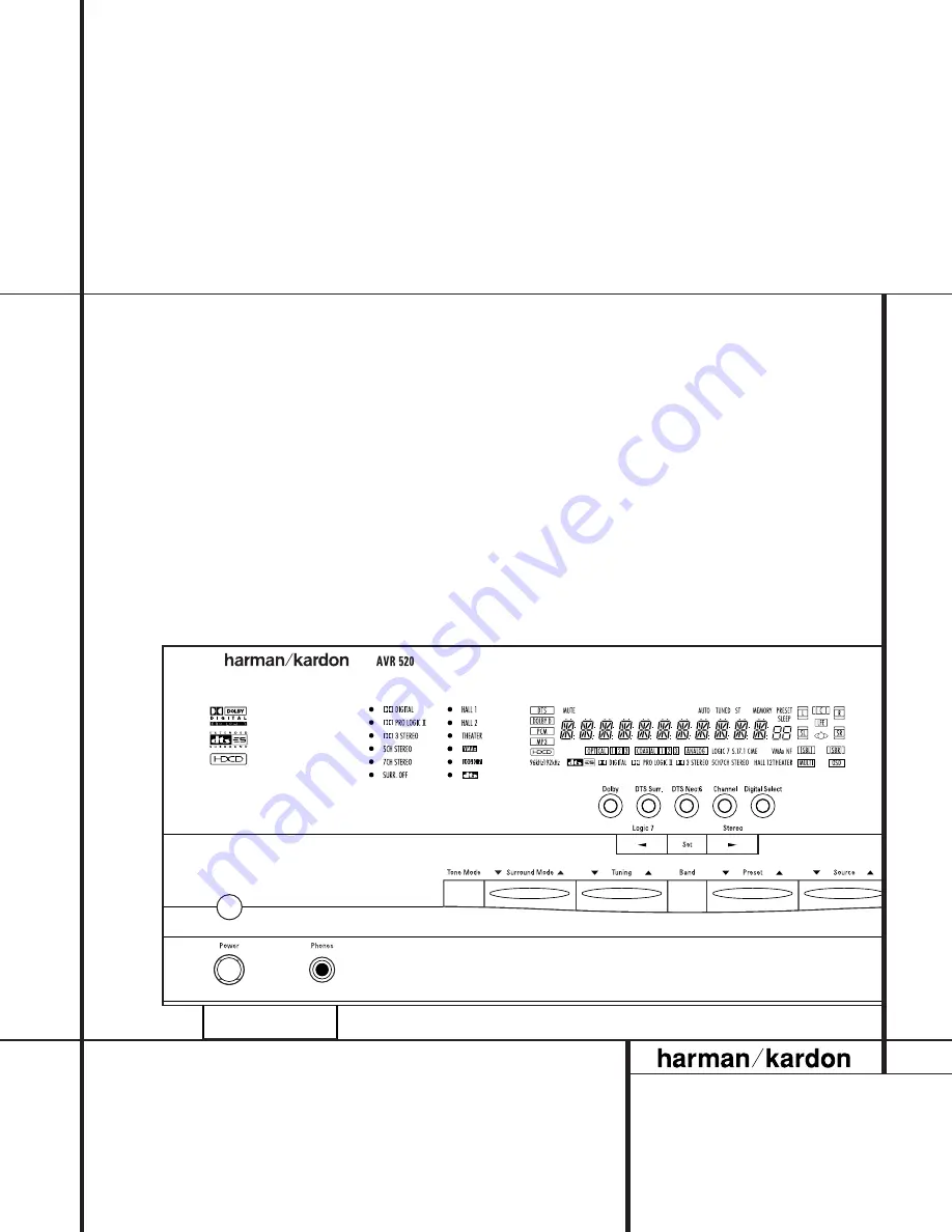
Page 5: ...oom speakers will automatically be turned off when the headphone jack is in use 5 Dolby Mode Selector Pressing this selec tor button cycles the AVR through the various Dolby surround modes The first press of the but ton switches the surround mode to the last Dolby surround mode that was in use Each sub sequent press selects the next mode in the fol lowing order 6 DTS Surround Mode Selector Pressin...
Page 6: ...ctor Press this button to select Auto or Manual tuning When the button is pressed so that the AUTO Indicator X lights the tuner will search for the next station with an acceptable signal when the Tuning Selector ué is pressed When the but ton is pressed so that the AUTO Indicator X is not lit each press of the Tuning Selector ué will increase the frequency See page 31 for more information on using...
Page 7: ...t is currently the input source for the AVR 520 Main Information Display This display delivers messages and status indications to help you operate the receiver See pages 8 9 for a complete explanation of the Information Display Remote Sensor Window The sensor behind this window receives infrared signals from the remote control Aim the remote at this area and do not block or cover it unless an exte...
Page 8: ...ted I Dolby 3 Stereo Indicator This indicator lights when the Dolby 3 Stereo mode has been selected J Logic 7 Mode Indicators These indica tors light to indicate that one of the Logic 7 modes is in use Along with the main Logic 7 indicator either 5 1 or 7 1 will light to indicate the selected speaker configuration One of the three letters to the far right of this segment will light to show which v...
Page 9: ... s preset memory number See page 32 for more information on tuner presets T Sleep Indicator This indicator lights when the Sleep function is in use The numbers in the Preset Number Sleep Timer R indicator will show the minutes remaining before the AVR 520 goes into the Standby mode See page 28 for more information on the Sleep function U Memory Indicator This indicator flashes when entering preset...
Page 10: ... as follows Front Left White Front Right Red Center Green Surround Left Blue Surround Right Gray Surround Back Left Brown Surround Back Right Tan Subwoofer Purple Digital Audio Orange Composite Video Yellow Component Video Y Green Component Video Pr Red Component Video Pb Blue 8 Channel Direct Inputs When an option external processor or playback device with 6 1 or 7 1 audio capability is in use co...
Page 11: ... connected to one of the two Component Video Inputs ac is selected the signal will be sent to these jacks c DVD Component Video Inputs Connect the Y Pr Pb component video outputs of a DVD player to these jacks d Remote IR Output This connection per mits the IR sensor in the receiver to serve other remote controlled devices Connect this jack to the IR IN jack on Harman Kardon or other compatible eq...
Page 12: ... u Tuning Up Down v OSD Button w Dolby Mode Select Button x DTS Digital Mode Selector y Logic 7 Mode Select Button z Transport Controls Light Button 28 Skip Up Down Button 29 Stereo Mode Select Button 30 DTS Neo 6 Mode Select 31 Macro Buttons 32 Disc Skip Button 33 Preset Up Down 34 Clear Button 35 Memory Button 36 Delay Prev Ch 37 Button 38 Speaker Select 39 Multiroom 40 Volume Up Down 41 SPL Ind...
Page 13: ...n to place the unit in the Sleep mode After the time shown in the display the AVR 520 will auto matically go into the Standby mode Each press of the button changes the time until turn off in the following order Note that this button is also used to change channels on your TV when the TV is selected When the AVR 520 remote is being programmed with the codes to operate another device this button is ...
Page 14: ...CRs and cassette decks are selected using the device Input Selectors e these buttons may function as Chapter Step or Track Advance Clear Button Press this button to clear incorrect entries when using the remote to directly enter a radio station s frequency Memory Button Press this button to enter a radio station into the AVR 520 s preset memory Once the MEMORY Indicator U flashes you have five sec...
Page 15: ... Skip Press this button to change discs on compatible Harman Kardon CD or DVD changer or players Volume Up Down When used in the room where the AVR 520 is located press this button to raise or lower the volume in that room When it is used in a remote room with a sensor that is connected to the Multiroom IR jack f this button will raise or lower the vol ume in the remote room Play Forward Reverse S...
Page 16: ...isting with UL CSA or other appropriate testing agency stan dards Questions about running cables inside walls should be referred to your installer or a licensed electrician who is familiar with the NEC and or the applicable local building codes in your area When connecting wires to the speakers be cer tain to observe proper polarity Note that the positive terminal of each speaker connection now ca...
Page 17: ...one sensor is needed Simply use this unit s sensor or a remote eye by running a connection from the Remote IR Output jack d to the Remote IR Input jack on Harman Kardon or other compati ble equipment Multiroom IR Link The remote room IR receiver should be connected to the AVR 520 via standard coaxial cable Plug the IR connection cable into the Multiroom IR Input jack f on the AVR 520 s rear panel ...
Page 18: ... compared to the left and right speakers A Front Channel Speaker Installation With Direct View TV Sets or Rear Screen Projectors B Rear speaker mounting is an alternate location for 5 1 systems It is required for 7 1 operation When the AVR 520 is used in 5 1 channel oper ation the preferred location for surround speakers is on the side walls of the room at or slightly behind the listening position...
Page 19: ...SD system is also available allowing you to make adjustments directly by pressing the appropriate buttons on the front panel or remote control for the specific parameter to be adjusted For example to change the digital input for any of the sources press the Digital Select Button Ûq on the front panel or remote To use the full OSD menu system press the OSD Button v When the menu is on the screen pr...
Page 20: ... the screen until the cursor is next to COAXIAL 3 Then press the Buttons o so that the word OUT is highlighted Note that the Input Output Status Indicator will turn red indicating that the jack is now a record output NOTE A signal will be sent to this jack only when the input selected for use by the AVR 520 is digital Digital signals will be passed through regardless of their format and which digi...
Page 21: ...Display Y Press the Button n with in three seconds to select the desired setting When all settings for the surround setup have been made press the Buttons n so that the cursor is next to BACK TO MASTER MENU and press the Set Button p to return to the Master menu On the DTS menu the selection choices made with the Buttons o on the remote are determined by a combination of the type of DTS program ma...
Page 22: ...ibes your system based on the speaker definitions shown below When SMALL is selected low frequency center channel sounds will be sent only to the subwoofer output If you choose this option and there is no subwoofer connected you will not hear low frequency sounds from the center channel speaker When LARGE is selected a full range output will be sent to the center speaker output and NO center chann...
Page 23: ...t takes for sound to reach your ears from the front versus surround speakers differs You may compensate for this difference through the use of the delay settings to adjust the timing for the speaker placement and acoustic conditions in your listening room or home theater The factory setting is appropriate for most rooms but some installations create an uncom mon distance between the front and surr...
Page 24: ... seconds press the 5 Button r on the remote if your system is configured for 5 1 operation with standard speakers or the 7 Button r on the remote if your system is configured for 6 1 7 1 operation with a full speaker complement including rear surround speakers Once the correct channel configuration button has been pressed the test noise will be heard from the front left speaker 5 At this point EzS...
Page 25: ...en for all channels When it is red the level is too high when it is amber the level is too low Press the SPL Indicator Select c button when you are finished to turn the sensor and Indicator off NOTE The subwoofer output level is not adjustable using the test tone To change the subwoofer level follow the steps for Output Level Trim Adjustment on page 32 When all channels have an equal volume level ...
Page 26: ... menu the 5 1 versions of Logic 7 modes are available when the 5 1 option is chosen while the 7 1 versions of Logic 7 produce a full sound field presentation including back surround speakers when the 6 1 7 1 option is chosen The Logic 7 C or Cinema mode should be used with any source that contains Dolby Surround or similar matrix encoding Logic 7 C delivers increased center channel intelligibility...
Page 27: ...n headphones are being used the Far Field mode will appear to push the sound field away from your ears reducing the inside the head sensation often experienced when using headphones 5 Channel Stereo This mode takes advantage of multiple speakers to place a stereo signal at both the front and No delay available in 7 Channel Stereo back of a room Depending on whether the AVR has been configured for ...
Page 28: ...e speaker configura tion output levels crossover frequency and night mode status that were entered during the configuration process for that source The front panel Video 4 Inputs Ô may be used to connect a device such as a video game or camcorder to your home entertainment system on a temporary basis As the input source is changed the new input name will appear momentarily as an on screen display ...
Page 29: ...ivers five discrete channels left front center right front left surround and right surround Each channel reproduces full fre quency range 20Hz to 20kHz and offers dra matically improved dynamic range and significant improvements to signal to noise ratios In addi tion digital systems have the capability to deliver an additional channel that is specifically devoted to low frequency information This ...
Page 30: ...L and R indicators will light as analog signals have only left and right channels Digital signals however may have two five six or seven separate channels depending on the program material the method of transmission and the way in which it was encoded When a digital signal is playing the letters in these indi cators will light in response to the specific sig nal being received It is important to n...
Page 31: ...akers and low pow ered amplifiers typically used with computers To take advantage of the AVR 520 s MP3 capa bilities simply connect the PCM output of a computer s sound card or the PCM output of a portable digital audio device to either the rear panel Digital Inputs or the front panel Digital Inputs Ó When the digital signal is available the MP3 Bitstream Indicator A will light and the audio will ...
Page 32: ...ged to an output the setting will remain as long as the AVR 520 is turned on unless the setting is changed in the OSD menu system as described above Note however that once the AVR 520 is turned off the setting is cancelled When the unit is turned on again the front panel jacks will return to their normal default setting as an input If you wish to use their jacks as an output at a future time the s...
Page 33: ...tons n to move the on screen cursor so that it is next to RETURN TO MAS TER MENU and then press the Set Button p if you wish to go back to the main menu to make other adjustments If you have no other adjustments to make press the OSD Button v to exit the menu system NOTE The output levels may be separately trimmed for each digital and analog surround mode If you wish to have different trim levels ...
Page 34: ... the on screen cursor is next to the VOLUME DEFAULT line by pressing the Buttons n as needed Next press the Button so that the word ON is high lighted in the video display Next press the Button n once so that the on screen cur sor is next to the DEFAULT VOL SET line To set the desired turn on volume press the Buttons o until the desired volume level is shown on the DEFAULT VOL SET line Note that t...
Page 35: ...rom the screen Time Out Time Out is a safety measure to prevent image retention of the menu text in your monitor or projector which might happen if it were left on indefinitely However some viewers may prefer a slightly longer or shorter period before the Time Out display To change the Full OSD Time Out you will need to make an adjustment in the ADVANCED menu Figure 9 To start the adjustment press...
Page 36: ... long as an IR feed to the AVR 520 has been established from the remote room using any of the buttons on either remote will control the remote location volume î change the tuner frequency uç change the tuner preset or mute the output If the Remote IR Output Jack d on the AVR 520 is connected to an IR Input jack on compatible Harman Kardon audio components such as CD DVD or cassette players the tra...
Page 37: ...s not seem to operate properly you may wish to program the correct code using the Auto Search method that follows 1 Turn on the unit that you wish to include in the AVR 520 remote 2 Press the Input Selector e for the type of product to be entered e g VCR TV and the Mute button at the same time Hold both buttons until the red light under the Input Selector e stays lit Note that the next step must t...
Page 38: ... be erased have been pressed press the Learn Button h to complete the process To erase all codes within a single device follow these steps 1 Press and hold both the Input Selector efg for which you wish to erase the codes and the Learn Button h 2 When the red LED under the Input Selector turns red and the Program SPL Indicator c flashes amber release the buttons 3 Press and release the Input Selec...
Page 39: ...duct When you press any one of the selectors it will briefly flash in red to indicate that you have changed the device being controlled When operating a device other than the AVR 520 the controls may not correspond exactly to the function printed on the remote or button Some commands such as the volume control are the same as they are with the AVR 520 Other buttons will change their function so th...
Page 40: ... by the AVR 520 or the remote To program the remote for Channel Control Punch Through follow these steps 1 Press the Input Selector Button e for the device you wish to have the channel con trol associated with and the Mute Button at the same time until the red light appears under the Input Selector e and the Program SPL Indicator c flashes amber 2 Press the Volume Down Button The Program SPL Indic...
Page 41: ...second VCR first press the CBL SAT Input Selector e and the Mute Button at the same time until the red light glows under the CBL SAT e button Press the VCR e Button followed by the three digit code for the specific model you wish to control Finally press the CBL SAT Button e again Resetting the Remote Memory As you add components to your home theater system occasionally you may wish to totally rep...
Page 42: ...CDR Select Channel Channel Channel 20 Night Night Mode Select Subtitle On Off CDR Select 21 Multiroom Multiroom Select 22 Volume Down Volume Down Input Level Down Volume Down Volume Down Volume Down 23 Channel Guide Channel Trim Title Info Guide Info Guide 24 Move Adjust Up Up Up Up Up Up 25 Speaker Menu Speaker Adjust Menu Intro Scan Menu Menu Menu Menu 26 fi Move Adjust Left Left Left Left Left L...
Page 43: ...SD OSD 50 D Skip Disc Skip Disc Skip 51 Preset Down Preset Tune Down Slow Rev 52 M1 53 M2 54 M3 55 M4 56 Dolby Dolby Modes 57 DTS SURR DTS Digital Modes 58 DTS Neo 6 DTS Neo 6 Select 59 Logic 7 Logic 7 Select 60 Stereo Stereo Mode Select 61 Skip Down Skip Skip Scan 62 Skip Up Skip Skip Scan 63 Rewind R Search R Search Rewind Rewind 64 Play Play Play Play Play 65 Fast Forward F Search F Search Fast...
Page 44: ...LECTROHOME 074 132 EMERSON 001 012 033 045 048 049 051 052 091 107 132 137 139 141 157 158 162 205 FISHER 013 058 FUNAI 033 045 FUTURETECH 045 GE 001 014 015 038 057 070 071 107 121 133 141 145 163 199 GOLDSTAR 011 093 097 101 103 104 107 110 113 118 128 132 GRUNDIG 193 HALL MARK 107 HARMAN KARDON 201 HITACHI 001 011 015 016 017 018 029 043 072 132 144 147 INFINITY 148 INKEL 120 JBL 148 JC PENNEY ...
Page 45: ...ALISTIC 013 025 045 048 195 196 197 RUNCO 152 153 SAA 183 SAMPO 001 059 107 SAMSUNG 051 085 092 096 104 107 118 124 128 132 145 SANYO 013 026 027 037 041 054 058 078 SCOTT 033 045 049 107 132 SEARS 011 013 021 033 035 058 078 092 107 132 145 SHARP 011 020 025 028 033 034 077 132 154 SIEMENS 084 SIGNATURE 069 SONY 043 067 075 117 130 136 194 212 SOUNDESIGN 003 033 045 107 SPECTRICON 103 SSS 011 045...
Page 46: ...3 015 016 017 FUNAI 040 133 GE 037 039 067 076 093 095 124 127 GO VIDEO 113 117 GOLDSTAR 018 019 026 087 092 100 107 GRAETZ 136 HARMAN KARDON 018 049 HITACHI 011 040 048 067 118 130 INSTANT REPLAY 037 039 ITT 136 JCL 037 039 JC PENNEY 018 019 021 039 045 070 087 JENSEN 048 JVC 018 037 039 048 052 054 059 064 111 130 132 KENWOOD 020 044 048 052 LLOYD 040 LXI 019 020 040 087 MAGIN 045 MAGNAVOX 037 0...
Page 47: ...ALORA 020 SAMSUNG 038 045 088 090 091 093 095 098 099 101 105 106 109 SANSUI 028 048 052 116 147 166 SANYO 003 014 017 020 115 SCHAUB LORENZ 136 SCOTT 023 043 098 110 112 SEARS 003 015 016 017 019 020 026 037 047 077 084 087 SHARP 037 058 129 156 SHINTOM 030 SONY 003 016 037 056 060 061 062 080 081 082 129 SOUNDESIGN 040 STS 019 SYLVANIA 037 039 040 063 071 SYMPHONIC 040 TANDY 017 040 TASHICO 134 ...
Page 48: ...RABA 117 FUNAI 126 GE 164 GENEXXA 017 096 108 GOLDSTAR 016 087 HAITAI 099 214 HARMAN KARDON 001 002 025 040 054 190 218 219 HITACHI 049 093 INKEL 026 027 216 JC PENNEY 021 066 098 147 JENSEN 153 JVC 029 176 195 196 KENWOOD 014 020 023 030 062 078 079 148 151 176 178 181 KYOCERA 012 LOTTE 108 LUXMAN 018 035 077 102 LXI 066 164 MAGNAVOX 039 051 113 MARANTZ 043 051 058 084 191 192 193 MCINTOSH 194 MC...
Page 49: ...049 056 057 058 093 095 104 105 108 164 166 ROTEL 051 SAE 051 SAMSUNG 028 SANSUI 047 051 081 134 157 172 SANYO 033 057 068 082 095 168 SCOTT 108 SEARS 066 SHARP 020 058 073 105 114 151 159 167 180 181 SHERWOOD 003 026 027 041 058 105 133 SIGNATURE 040 SONY 060 103 115 116 118 132 139 163 205 206 207 208 212 217 SOUNDSTREAM 124 STS 012 SYLVANIA 051 SYMPHONIC 059 110 TAEKWANG 177 TANDY 096 TEAC 011 ...
Page 50: ...OOD 007 050 LG 005 055 064 LOTTE 008 MAGNAVOX 033 056 MARANTZ 033 059 MITSUBISHI 023 036 NAD 010 062 ONKYO 009 015 048 OPTIMUS 011 050 PANASONIC 024 025 030 034 035 044 052 PHILIPS 033 056 PIONEER 012 020 038 041 046 047 065 PROCEED 060 PROSCAN 003 004 037 RCA 003 004 018 037 RUNCO 027 SAMSUNG 031 053 054 SANYO 013 049 SHARP 021 028 050 SONY 015 029 043 045 TECHNICS 026 THOMSON 003 004 TOSHIBA 009...
Page 51: ...OUSTON TRACKER 463 HUGHES 372 437 HYTEK 359 JANIEL 366 JERROLD 367 454 464 468 KATHREIN 410 LEGEND 453 LUXOR 368 MACOM 317 365 369 370 371 MAGNAVOX 461 473 MEMOREX 453 NEXTWAVE 423 424 NORSAT 373 374 OPTIMUS 466 PANASONIC 366 469 PANASONIC DBS 457 PANSAT 420 PERSONAL CABLE 418 PHILIPS 375 PICO 407 PRESIDENT 326 404 PRIMESTAR 412 454 464 475 RCA 301 408 436 439 458 465 REALISTIC 349 377 480 SAMSUNG...
Page 52: ...29 032 060 GENERAL 210 GENERAL INSTRUMENT 168 GOLDEN CHANNEL 037 GOODMIND 112 HAMLIN 055 056 061 099 100 101 117 175 207 208 HITACHI 001 061 188 HOSPITALITY 074 080 JASCO 111 JERROLD 001 002 003 011 015 016 017 073 093 095 096 097 162 167 LINDSAY 118 M NET 043 MACOM 040 191 MAGNAVOX 017 019 068 082 MEMOREX 058 MOVIE TIME 035 039 NSC 022 035 044 075 190 OAK 023 038 043 059 094 196 197 PACE 179 PANA...
Page 53: ... 052 110 183 184 203 204 SEAM 121 SHERITECH 029 SIGNAL 037 SIGNATURE 001 188 SL MARX 037 SPRUCER 053 081 177 189 STARCOM 002 011 015 016 163 STARGATE 015 037 120 SYLVANIA 071 TADIRAN 037 TANDY 024 TELECAPATION 028 TEXSCAN 036 071 TFC 122 TIMELESS 123 TOCOM 045 046 062 170 205 TOSHIBA 058 UNIKA 014 021 031 UNITED CABLE 011 059 UNIVERSAL 012 014 021 031 033 034 039 042 113 VIDEOWAY 124 211 VIEWSTAR ...
Page 54: ...rs fluorescent lights motors or other electrical appliances Letters flash in the channel indicator Digital audio feed paused Resume play for DVD display and digital audio stops Check that Digital Input is selected Processor Reset In the rare case where the unit s operation or the displays seem abnormal the cause may involve the erratic operation of the system s memory or microprocessor To correct ...
Page 55: ... 1Vp p 75 ohms Video Frequency Response Composite and S 10Hz 8MHz 3dB Video Frequency Response Component 10Hz 30MHz 3dB General Power Requirement AC 120V 60Hz Power Consumption 78W idle 694W maximum 2 channels driven Dimensions Max Width 17 3 inches 440mm Height 6 5 inches 165mm Depth 17 1 inches 435mm Weight 35 lb 15 9 kg Depth measurement includes knobs buttons and terminal connections Height me...
Page 56: ...250 Crossways Park Drive Woodbury New York 11797 www harmankardon com 2002 Harman Kardon Incorporated Part No J90200022100 Rev 1 02 2002 ...