background image

5

Lowes.com/harborbreeze

SAFETY INFORMATION 

Please read and understand this entire manual before attempting to assemble, operate, or install the 
product.
•  Before you begin installing the fan, disconnect the power by removing fuses or turning off circuit 

breakers.

•  Make sure all electrical connections comply with local codes, ordinances, or the National Electrical 

code. Hire a qualifi ed electrician or consult a do-it-yourself wiring handbook if you are unfamiliar 
with installing electrical wiring.

•  Make sure the installation site you choose allows a minimum clearance of 7 ft. from the blades to 

the fl oor and at least 30 in. from the ends of the blades to any obstruction. 

•  If you are mounting the fan to a ceiling outlet box, use a METAL octagonal outlet box.
•  Secure the box directly to the building structure. The outlet box and its support must be able to 

support the moving weight of the fan (at least 35 lbs.). Do NOT use a plastic outlet box.

•  After you install the fan, make sure all connections are secure to prevent the fan from falling.
•  For supply connections, if the conductor of a fan is identifi ed as a grounded conductor, then it 

should be connected to a grounded conductor power supply. If the conductor of a fan is identifi ed 
as an ungrounded conductor, then it should be connected to an ungrounded conductor power 
supply. If the conductor of a fan is identifi ed for equipment grounding, then it should be connected 
to an equipment-grounding conductor.

•  This device complies with Part 15 of the FCC Rules. Operation is subject to the following two 

conditions: (1) This device may not cause harmful interference, and (2) this device must accept any 
interference received, including interference that may cause undesired operation.

Note

: This equipment has been tested and found to comply with the limits for Class B digital 

device, pursuant to part 15 of the FCC Rules. These limits are designed to provide reasonable 
protection against harmful interference in a residential installation. This equipment generates, 
uses and can radiate radio frequency energy and, if not installed and used in accordance with 
the instructions, may cause harmful interference to radio or television reception, which can be 
determined by turning the equipment off and on, the user is encouraged to try to correct the 
interference by one or more of the following measures:

– Reorient or relocate the receiving antenna.
– Increase the separation between the equipment and the receiver.
– Connect the equipment into an outlet on a circuit different from that to which the receiver is 

connected.

– Consult the dealer or an experienced radio/TV technician for help.

Note

: For a Class A digital device, statements of 15. 105(a) must be included when appropriate for 

the device in question.

•  The net weight of this fan is: 20.68 lbs.

WARNING

:

•  Do not install or use this fan if any part is damaged or missing.
•  To reduce the risk of fi re, electrical shock, or personal injury, wire connectors provided with this 

fan are designed to accept only one 12-gauge house wire and two lead wires from the fan. If your 
house wire is larger than 12 gauges or there is more than one house wire to connect to the two fan 
lead wires, consult an electrician for the proper size wire connectors to use. Before cutting, drilling 
or hammering, verify their location. If needed, contact your electrician, plumber or service person.

Summary of Contents for Santa Ana LP8294LBN

Page 1: ...0 643 0067 8 a m 6 p m EST Monday Thursday 8 a m 5 p m EST Friday 1 EB13442 ATTACH YOUR RECEIPT HERE Serial Number ____________ Purchase Date ____________ Harbor Breeze is a registered trademark of LF...

Page 2: ...Contents 4 Safety Information 5 Preparation 6 Initial Assembly Instructions 7 Wiring Instructions 13 Final Assembly Instructions 14 Operating Instructions 16 Blade Balancing Instructions 19 Care and M...

Page 3: ...s 1 B Hanger Bracket 1 J Blade Holder Arm 2 C Downrod 1 K Blade 2 D Ceiling Canopy 1 L Bulb 1 E Canopy Screw Cover 1 M Receiver preassembled to Motor A 1 F Motor Coupling Cover 1 N Remote 1 G Lower Ho...

Page 4: ...ng Cover Screw preassembled to Motor A Qty 6 GG HH II JJ Hanger Ball Set Screw preassembled to Downrod C Qty 1 Hanger Ball Pin preassembled to Downrod C Qty 1 Downrod Clip preassembled to Downrod C Qt...

Page 5: ...may not cause harmful interference and 2 this device must accept any interference received including interference that may cause undesired operation Note This equipment has been tested and found to co...

Page 6: ...g fixtures are not acceptable for fan support and may need to be replaced Consult a qualified electrician if in doubt This fan is to be used in dry locations only PREPARATION Before beginning assembly...

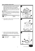
Page 7: ...motor A Retain the screws for later Hardware Used EE Downrod Support Set Screws x 2 1 A EE 2 Remove the preassembled upper housing cover screws FF from the top of the motor A Retain these screws for l...

Page 8: ...he other blade holder arm J WARNING To reduce the risk of personal injury do not bend the blade holders when installing balancing the blades or cleaning the fan Do not insert foreign objects in betwee...

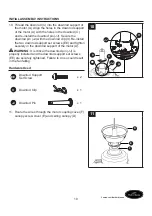
Page 9: ...hanger ball portion of the downrod C Retain the hanger ball pin HH and hanger ball for later Hardware Used GG Hanger Ball Set Scre x 1 HH Hanger Ball Pin x 1 7 HH C GG 8 Remove the preassembled downro...

Page 10: ...install the two downrod support set screws EE and tighten securely in the downrod support of the motor A WARNING It is critical the downrod pin JJ is properly installed and the downrod support set sc...

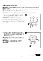
Page 11: ...HH is captured in the groove in the top of the downrod C Pull the hanger ball up tight against the hanger ball pin HH Securely tighten the preassembled hanger ball set screw GG CAUTION A loose set scr...

Page 12: ...th the outlet box WARNING The outlet box must be securely anchored The hanger bracket must seat firmly against the outlet box If the outlet box is recessed remove wallboard until the bracket contacts...

Page 13: ...ector CC Securely connect the white fan motor wire to the white supply neutral wire and secure the connection with a wire connector CC Securely connect the black fan motor wire to the black supply wir...

Page 14: ...completely inside the canopy housing and not pinched between the housing and the ceiling Hardware Used KK Shoulder Screw x 1 1 D KK 2 Securely attach and tighten the canopy screw cover E over the shou...

Page 15: ...ad Screw x 6 4 K J BB 5 Connect the pin connectors from the socket plate assembly H to the pin connectors from the motor A 5 A H 6 Remove one of the preassembled socket plate assembly screws MM inside...

Page 16: ...r to use To reduce the risk of fire use a 100 watt max type T4 minican JD E11 tungsten halogen bulb Turn off the wall switch and allow the bulb to cool for 10 minutes before relamping 7 L 8 Securely a...

Page 17: ...o prevent damage to the remote Be sure to store the remote away from excess heat or humidity 2 N 12V Q 3 Follow these steps to set the remote N a Slide the dip switch to 1 inside the battery compartme...

Page 18: ...dimming Light button Fan speed Walk Away Light Delay Turns the fan and light off after 1 minute During walk away light delay mode press any other key to cancel the function Home Shield The fan is tur...

Page 19: ...each blade K Note which blade K has the least wobble On that blade K install the balancing clip DD to the top edge of the blade K near the motor A Start the fan and observe wobble Stop the fan and mo...

Page 20: ...d scratching the finish Abrasive cleaning agents are not required and should be avoided to prevent damage to the finish Periodically check that all hardware is tight and secure Periodic light dusting...

Page 21: ...e loose 4 Wire connectors inside the housing are rattling 5 There is a motor noise caused by a solid state variable speed control 6 The screws holding the blades to the blade holders are loose 1 Attac...

Page 22: ...er Any damage to the ceiling fan by accident misuse or improper installation or by affixing accessories not produced by this warranty are at the purchaser s own responsibility The manufacturer assumes...

Page 23: ...ger Bracket APGAC110RBL C Hanger Ball Downrod Assembly ADRACT1 6LBN D Ceiling Canopy PPAC1005LBN E Canopy Screw Cover APPAC1101LBN F Motor Coupling Cover APPAC1403LBN G Lower Hosing Assembly AP829404L...

Page 24: ...de lunes a jueves de 8 a m a 6 p m y los viernes de 8 a m a 5 p m hora est ndar del Este 24 ADJUNTE SU RECIBO AQU N mero de serie ____________ Fecha de compra ____________ Harbor Breeze es una marca r...

Page 25: ...28 Preparaci n 29 Instrucciones de ensamblaje iniciales 30 Instrucciones de cableado 36 QVWUXFFLRQHV GH HQVDPEODMH QDOHV 37 Instrucciones de funcionamiento 39 Instrucciones para equilibrar las aspas 4...

Page 26: ...pa 2 C Varilla 1 K Aspa 2 D Base para techo 1 L Bombilla 1 E Cubierta para el tornillo de la base 1 M Receptor preensamblado en el motor A 1 F Cubierta para el acoplador del motor 1 N Control remoto 1...

Page 27: ...eensamblado en el motor A Cant 6 GG HH II JJ Bola para colgar preensamblada en la varilla C Cant 1 Pasador de la bola para colgar preensamblado en la varilla C Cant 1 Sujetador de la varilla preensamb...

Page 28: ...sujeto a las siguientes dos condiciones 1 Este dispositivo no debe causar interferencia perjudicial y 2 deber aceptar cualquier interferencia recibida incluida la interferencia que pudiese causar la o...

Page 29: ...luminaci n no son aptas para sostener un ventilador SXHGH VHU QHFHVDULR UHHPSOD DUODV 6L WLHQH GXGDV FRQVXOWH D XQ HOHFWULFLVWD FDOL FDGR Este ventilador es apto solo para lugares secos PREPARACI N An...

Page 30: ...elante Aditamentos utilizados EE 7RUQLOORV GH MDFLyQ del soporte de la varilla x 2 1 A EE 2 Retire los tornillos preensamblados en la carcasa superior FF de la parte superior del motor A Guarde estos...

Page 31: ...IA Para reducir el riesgo de lesiones personales no doble los soportes de las aspas al instalarlos equilibrar las aspas o limpiar el ventilador No introduzca objetos extra os entre las aspas en movimi...

Page 32: ...la bola para colgar HH y la bola para colgar para pasos posteriores Aditamentos utilizados GG 7RUQLOOR GH MDFLyQ de bola para colgar x 1 HH Pasador de la bola para colgar x 1 7 HH C GG 8 Retire el pa...

Page 33: ...D YDULOOD DSULpWHORV UPHPHQWH DO VRSRUWH GH OD YDULOOD GHO PRWRU ADVERTENCIA Es fundamental que instale correctamente el pasador de la varilla JJ y que apriete UPHPHQWH ORV WRUQLOORV GH MDFLyQ GHO VRS...

Page 34: ...arilla C DOH OD EROD SDUD FROJDU UPHPHQWH DO SDVDGRU LMH ELHQ HO WRUQLOOR GH MDFLyQ GH OD EROD SDUD FROJDU preensamblada GG PRECAUCI N 8Q WRUQLOOR GH MDFLyQ RMR SRGUtD KDFHU que el ventilador se tamba...

Page 35: ...caja de salida debe estar bien asegurada La abrazadera para colgar debe estar bien asentada contra la caja de salida Si la caja de VDOLGD HVWi HPSRWUDGD UHWLUH HO SDQHO GH EUD SUHQVDGD hasta que la a...

Page 36: ...ores con un conector de cables CC Conecte de forma segura el conductor blanco del motor del ventilador al conductor blanco QHXWUR MH OD FRQH LyQ FRQ HO FRQHFWRU GH cables CC Conecte de forma segura el...

Page 37: ...y de no apretarlos entre la carcasa y el techo Aditamentos utilizados KK Tornillo de reborde x 1 1 D KK 2 RORTXH DMXVWH UPHPHQWH OD FXELHUWD SDUD HO WRUQLOOR de la base E sobre los tornillos de rebor...

Page 38: ...ores de los pasadores del ensamble de la placa del portal mpara H a los conectores de los pasadores del motor A 5 A H 6 Retire uno de los tornillos preensamblados del ensamble de la placa del portal m...

Page 39: ...sminuir el riesgo de incendios utilice una bombilla minican de tungsteno hal gena tipo T4 JD E11 de 100 vatios como m ximo Apague el interruptor de pared y deje enfriar la bombilla durante 10 minutos...

Page 40: ...ar el control remoto alejado del calor y humedad extremos 2 N 12V Q 3 Siga estos pasos para ajustar el control remoto N a Deslice el interruptor DIP a 1 dentro del compartimiento de la bater a y apagu...

Page 41: ...entilador Luz de retardo con sensor de movimiento Apaga el ventilador y la luz despu s de 1 minuto Durante el modo luz de retardo con sensor de movimiento presione cualquier otro bot n para cancelar l...

Page 42: ...K tiene el menor tambaleo Instale en dicha aspa K el sujetador de equilibrio DD en el borde superior del aspa K cerca del motor A Haga funcionar el ventilador y observe si hay tambaleo Detenga el ven...

Page 43: ...ntes limpiadores abrasivos son innecesarios y deben evitarse para no da ar el acabado Revise peri dicamente que todos los aditamentos est n ajustados y aseg relos Se recomienda una limpieza suave del...

Page 44: ...HVWiQ RMRV 4 Los conectores al interior de la carcasa repiquetean 5 El control de velocidad variable de estado s lido produce ruidos en el motor 6 Los tornillos que sujetan las aspas a los soportes de...

Page 45: ...l cita del comprador Cualquier da o al ventilador de techo producido por accidente uso indebido o instalaci n incorrecta o a causa de accesorios GH MDFLyQ TXH QR HVWiQ FXELHUWRV SRU HVWD JDUDQWtD VHUi...

Page 46: ...mble de la varilla bola para colgar ADRACT1 6LBN D Base para techo PPAC1005LBN E Cubierta para el tornillo de la base APPAC1101LBN F Cubierta para el acoplador del motor APPAC1403LBN G Ensamble de la...

Reviews: