64
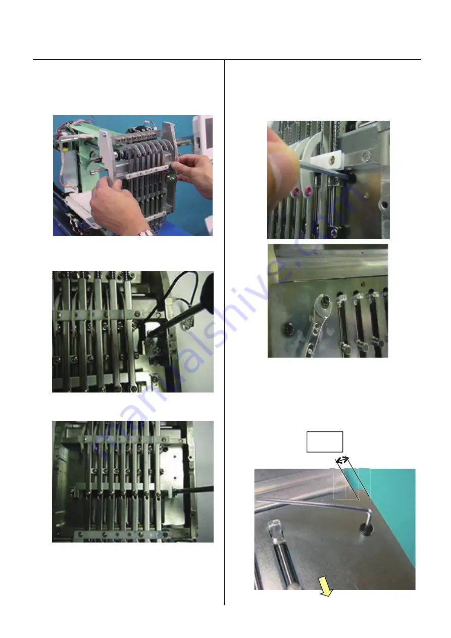
Fixing of needle bar boss guide plate
3-3-8
1. Referring to [3-2-1 Exchange of crank], remove moving
head.
2. Remove
Laser pointer unit ass'y.
3. R
Re
em
mo
ov
ve
e
B
Bl
lo
oc
ck
k
p
pl
la
at
te
e.
.
4.
Remove boss screw.
Please note that you need hexagonal driver for front screw
and spanner (4mm for rear nut as photo below.
5. Exchange of needle bar boss guide plate and fix it.
Push needle bar boss check plate to arrow marked
direction and keep the length of both sides equally
as photo below, then fix screws.
8mm
Summary of Contents for HCH-701-30
Page 1: ...Maintenance Manual for Embroidery Machine HCH 701 30 Version 2 4 HappyJapan Inc ...
Page 132: ...128 Electrical connection diagram 5 ...
Page 133: ...129 Electrical connection diagrams 5 ...
Page 134: ...130 List of electrical connection diagrams 5 ...
Page 137: ...130c HCD81222 LCD CE MX 基板組 ...
Page 138: ...130d HCD8116 TP switch board ass y 3 82 7 32 7 387487 2487 ...


