Chapter 8 Safety Settings
99
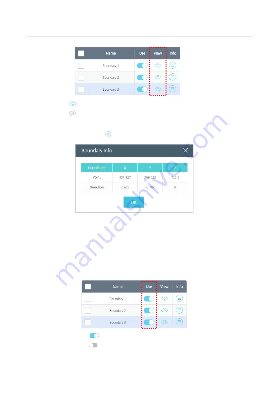
: To display in the preview screen.
: Not to display in the preview screen.
Press the
Info
icon to check the coordinates for the safety boundary.
Point
: Indicates the center of the 3-D where the center of the safety boundary is located.
Direction
: Indicates the direction(vector) for the border plane that can indicate a
collision with the safety border in the controller. (Blue Z-axis on the screen)
Applying safety boundaries
1.
Activate the boundary for use.
: To use
: Not to use
Summary of Contents for HCR-5
Page 1: ...HCR 5 Collaborative Robot User Manual Aug 2019 V 2 001 ...
Page 2: ......
Page 14: ......
Page 96: ...Chapter 8 Safety Settings 96 ...
Page 101: ...Chapter 8 Safety Settings 101 3 Press the OK button ...
Page 188: ...Chapter 15 Maintenance 188 4 When the confirmation window appears press YES ...
Page 192: ...192 Appendix B Certification Safety ...
Page 193: ...193 ...
Page 194: ...194 MD Machinery Directive ...
Page 195: ...195 LVD Low Voltage Directive ...
Page 196: ...196 EMC Electro Magnetic Compatibility ...
Page 197: ...197 Cleanroom Body ...
Page 198: ...198 Cleanroom Controller ...
Page 199: ...199 Appendix C Dimensions for Installation ...
Page 205: ......


