background image

22_

 network connection and setup

network connection and setup

You can set up the network settings according to your network configurations.

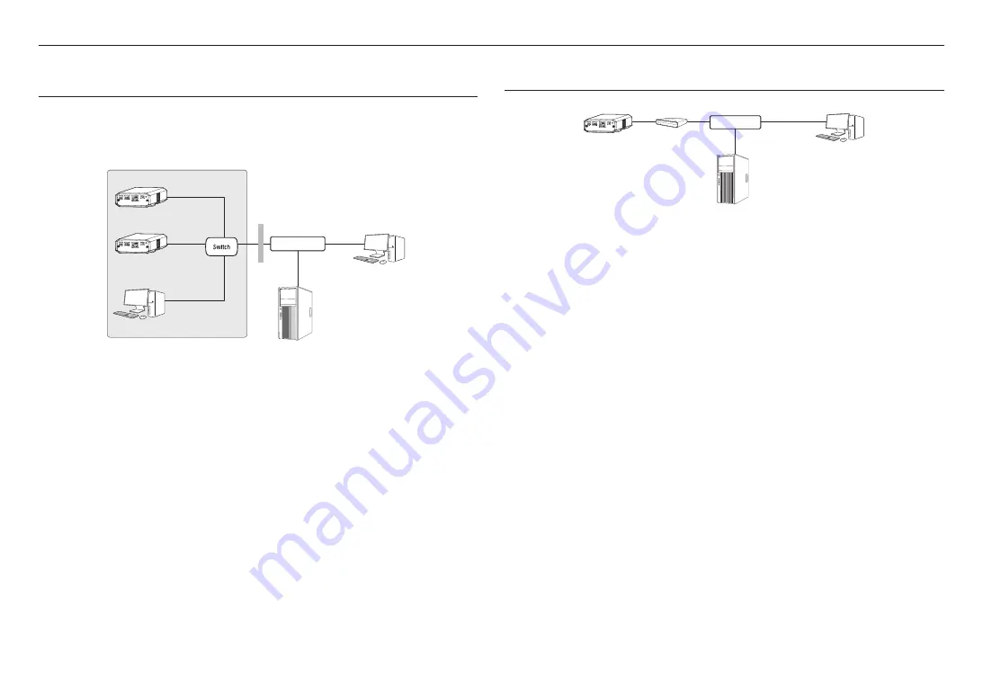
CONNECTING THE CAMERA DIRECTLY TO LOCAL AREA NETWORKING

Connecting to the camera from a local PC in the LAN

1. 

Launch an Internet browser on the local PC.

2. 

Enter the IP address of the camera in the address bar of the browser.

<Local Network>

4 3 2 1

DC 12V

NETWORK

VIDEO

RESET

GND : 1, 2

ALARM OUT : 3

ALARM IN : 4

4 3 2 1

DC 12V

NETWORK

VIDEO

RESET

GND : 1, 2

ALARM OUT : 3

ALARM IN : 4

Camera

Camera

Local PC

INTERNET

External Remote PC

DDNS Server 
(Data Center, KOREA)


M


`

A remote PC in an external Internet out of the LAN network may not be able to connect to the camera installed in the intranet 
if the port-forwarding is not properly set or a firewall is set. 
In this case, to resolve the problem, contact your network administrator.


`

By factory default, the IP address will be assigned from the DHCP server automatically. 
If there is no DHCP server available, the IP address will be set to 192.168.1.100. 
To change the IP address, use the Device Manager. 
For further details on Device Manager use, refer to “

Using Device Manager

”. (Page 23)

CONNECTING THE CAMERA DIRECTLY TO A DHCP BASED DSL/CABLE 
MODEM

4 3 2 1

DC 12V

NETWORK

VIDEO

RESET

GND : 1, 2

ALARM OUT : 3

ALARM IN : 4

Camera

External Remote PC

DDNS Server 
(Data Center, KOREA)

DSL/Cable Modem

INTERNET

1. 

Connect the user PC directly with the network camera.

2. 

Run the Device Manager and change the IP address of the camera so that you can use the web browser 
on your desktop to connect to the Internet.

3. 

Use the Internet browser to connect to the web viewer. 

4. 

Move to [

Setup

] page.

5. 

Move to [

Network

] – [

DDNS

] and configure the DDNS settings.

6. 

Move to [

Basic

] – [

IP & Port

], and set the IP type to [

DHCP

].

7. 

Connect the camera, which was removed from your PC, directly to the modem.

8. 

Restart the camera.


M


`

For information on how to set DDNS, refer to the online help of Web Viewer.


`

For information on how to set the IP format, refer to the online help of Web Viewer.

Summary of Contents for Wisenet XNB-6002

Page 1: ...NETWORK CAMERA User Manual XNB 6002 SLA T1080FA SLA T2480A SLA T2480VA SLA T2880BA SLA T4680A SLA T4680VA SLA T4680DA SLA T4680DSA...

Page 2: ...correctness of the contents in this document but no formal guarantee shall be provided Use of this document and the subsequent results shall be entirely on the user s own responsibility Hanwha Techwi...

Page 3: ...7 This product is intended to be supplied by isolation power 18 If you use excessive force when installing the product the camera may be damaged and malfunction If you forcibly install the product usi...

Page 4: ...r the Ethernet PoE in accordance with IEEE 802 3af shall be a UL Listed device with the output evaluated as a Limited Power Source as defined in UL60950 1 or PS2 as defined in UL62368 1 Unit is intend...

Page 5: ...vice NETWORK CONNECTION AND SETUP 22 22 Connecting the Camera Directly to Local Area Networking 22 Connecting the Camera Directly to a DHCP Based DSL Cable Modem 23 Using Device Manager 23 Automatical...

Page 6: ...ARD SPECIFICATIONS Recommended capacity 16GB to 1TB MLC or 3D TLC type required Recommended Manufacturers SanDisk Transcend Samsung Western Digital Product Type High endurance Pro endurance WD Purple...

Page 7: ...2 Used for installation on the wall or ceiling Cable for the testing monitor 1 Used to test the camera connection to a portable display device WHAT S INCLUDED LENS MODULE OPTIONAL This is a lens modul...

Page 8: ...module Fixture screw 1 Applicable when a BRACKET is used Model Name Appearance Item Name Quantity Description SLA T2480A Lens Module 1 Quick Guide Optional 1 Tapping Screw 2 Used for installation on...

Page 9: ...to assemble pipe brackets Model Name Appearance Item Name Quantity Description SLA T2880BA Double sided tape 5 Used to fix brackets on glass Surface cleaner 1 Used to remove pollutants on surfaces whe...

Page 10: ...ceiling or wall Cable to connect lens module 1 Use this when connecting the main unit and lens module RJ12 Plug 1 Use this when adjusting the length of the cable to connect the lens module Model Name...

Page 11: ...ns module bracket 1 Use this for lens module installation Torx L wrench 1 Used to remove and attach the bracket Screw 1 Used to fix the direction of the lens module Cable to connect lens module 1 Use...

Page 12: ...r about 5 seconds to reboot the system J If you reset the camera the network settings will be adjusted so that DHCP can be enabled If there is no DHCP server in the network you must run the Device Man...

Page 13: ...SLA T1080FA SLA T2480A SLA T4680A Item Description a Lens Module This lens module is used to shoot video b Main unit connection terminal This terminal is connected to the main unit through the cable...

Page 14: ...ables can cause damage to the product or a fire For safety purposes keep anyone else away from the installation site And put aside personal belongings from the site just in case The power must be turn...

Page 15: ...SLA T2480A SLA T4680A 1 Use two screws provided or remove protective film to use the double sided tape on the bottom side of the lens module bracket to install the lens module bracket J Remove foreign...

Page 16: ...cket 4 Tighten the screws in the screw hole on the bracket This only applies to the SLA T2480VA 5 Organize the cable separately within 1m from the lens module Installing the lens module in the main un...

Page 17: ...aterproof gasket Adjust the length of the cable for connecting the lens module The length of the cable for connecting the main unit and lens module can be adjusted Please follow the steps in the corre...

Page 18: ...IN USB CAM AUDIO OUT AUDIO IN USB CAM J Do not insert the Micro SD card while it s upside down by force Otherwise it may damage the Micro SD card AUDIO OUT AUDIO IN USB CAM Removing a Micro SD card G...

Page 19: ...E and DC 12 V are simultaneously turned on the device power will be supplied by both of PoE and DC 12V You can also use a router featuring PoE to supply power to the camera Use PoE that is compliant w...

Page 20: ...N10 NANO NETGEAR WNA3100M IODATA WN G150UMW IODATA WN S150UM TOTOLINK N300UM Connecting to Audio Input Output AUDIO OUT AUDIO IN USB CAM Network Speaker Microphone Microphone Speaker PC 1 Connect the...

Page 21: ...o the GND port Alarm In Wiring Diagram Sensor GND RESISTOR ALARM IN 5mA SINK RESISTOR RESISTOR VCC_3 3V DIODE GND MLCC TRANSISTOR External connection Inside of the camera To connect the alarm out If d...

Page 22: ...signed from the DHCP server automatically If there is no DHCP server available the IP address will be set to 192 168 1 100 To change the IP address use the Device Manager For further details on Device...

Page 23: ...TP Port Used to access the camera using the Internet browser defaulted to 80 RTSP Port A port that controls real time streaming The initial value is 554 If using a Broadband Router IP Address Enter an...

Page 24: ...layed click OK MANUALLY REGISTERING CAMERA If the camera cannot be found using search function the camera can be registered remotely by manually inserting IP information if the camera is connected to...

Page 25: ...etting is an example of setting CISCO IP router The settings may differ depending on the connected Broadband Router model For more information refer to the user manual of the applicable router Setting...

Page 26: ...TERNET On a remote computer that is not in the Broadband Router s network cluster is not allowed users can access cameras within a Broadband Router s network by using the camera s DDNS URL 1 Before yo...

Page 27: ...tem in support of the UPnP protocol 2 Click the camera name for search In the Windows operating system click the camera name searched from the network menu The login window is displayed Connecting via...

Page 28: ...or memorizing it LOGIN Whenever you access the camera the login window appears Enter the User ID and password to access the camera 1 Enter admin in the User name input box The administrator s ID admin...

Page 29: ...ears If the transmission method is set to multicast check whether there is a router that supports multicast in the LAN the camera is connected to Voice is not recorded even though audio input settings...

Page 30: ...where and how they can take these items for environmentally safe recycling Business users should contact their supplier and check the terms and conditions of the purchase contract This product and it...

Page 31: ......

Reviews: