24
FMS 1 - Fluorescence Monitoring System
© 2017 Hansatech Instruments Ltd
the FMS. However data upload of multiple files from instrument memory will take longer.
3.2
Operating the FMS
The FMS is designed to accommodate two different operating modes:
• “PC mode” - the control unit is serially linked to the PC with commands issued from “Modfluor”
under “real-time” control from the PC keyboard
• “Local mode” - (
) the control unit is used autonomously with measurement commands
issued via pre-loaded scripts accessed via the four-button keyboard on the control unit display
panel.
When the instrument is first used it will only contain two default scripts for measurement of Fv/Fm
and PSII. It is therefore sensible to use “PC mode” to test the system and generate further scripts
which are more suited to individual applications. “Local mode” operation is discussed in
3.2.1
“PC Mode” Operation Under Modfluor
Once the “Modfluor” program has successfully communicated with the control unit, it loads the
data recording screen.
3.2.2
The Recording Screen
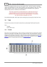
The default recording screen which is generated when the software is first initialised consists of
four areas:
·
The data recording area (A, Figure 2-1),
·
Instrument monitor bar (B, Figure 2-1),
·
“Drop-down” menu bar (C, Figure 2-1),
·
Instrument tool bar (D, Figure 2-1).
Summary of Contents for FMS1
Page 1: ......
Page 7: ...Section 1 Measurement Principles and Hardware ...
Page 21: ...Section 2 Software Installation System Operation Data Handling ...
Page 70: ...70 FMS 1 Fluorescence Monitoring System 2017 Hansatech Instruments Ltd ...
Page 71: ...Section 3 Stand Alone Instrument Operation and Data Upload ...
Page 83: ...83 Section 3 Stand Alone Instrument Operation and Data Upload 2017 Hansatech Instruments Ltd ...

