background image

11

Deutsch

A

B

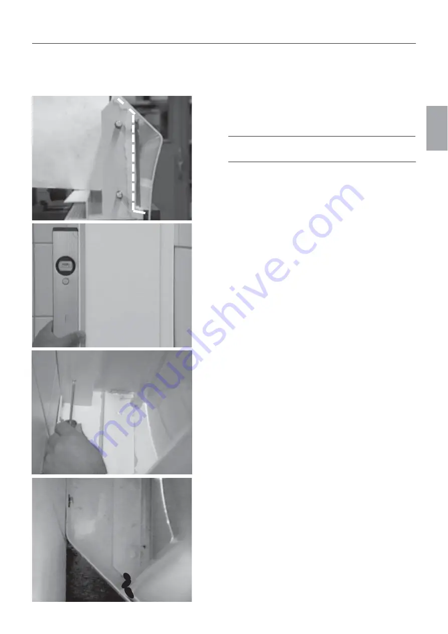
W a n d p r o f i l   m o n t i e r e n ,   E c k - A u f b a u

Wandprofile fixieren

Wandprofile in die Wandanschlußleiste stecken und auf
die Wanne stellen. Die Wandprofile mit der Duschwanne
verschrauben, Gleitringe, Unterlagscheiben  und Muttern
M12 verwenden.
Wandprofile mit der Wasserwaage senkrecht ausrichten.

Wandprofile mit der Wandanschlußleiste fixieren. Im
Wandprofil befinden sich drei Bohrungen; dieses Bohr-
bild mit einem Bohrer Ø3 auf die Wandausgleichsleiste
übertragen. Mit Linsen-Blechschrauben mit Kreuzschlitz
4,2x13 Wandprofil mit der Wandausgleichsleiste verbin-
den.

Wandprofile fixieren

Wandprofile mit dauerelastischem Fugenmaterial gegen die
Duschwanne abdichten.
Achten Sie auf eine vollflächige Abdichtung zwischen dem
Wandprofil 

A

 und der Aufkantung an der Duschwannen-

hinterkante 

B

. Verstreichen Sie die Silikonfuge bis zur Ober-

kante des Duschwannenprofils.

Auf den Befestigungsstegen des Wandprofils dauer-
elastisches Fugenmaterial auftragen. Den gesamten
Befestigungssteg lückenlos abdichten.

Bei Ausstellungsmontage: Installationskit statt
dauerelastischem Fugenmaterial verwenden.

Summary of Contents for 29040

Page 1: ...Montageanleitung 29040 29050 EL40 EL10 E C O 3 8 ECO 38 D u s c h t e m p e l 1 1 5 English Deutsch Français ...

Page 2: ...ellen 9 Wandprofil montieren Eck Aufbau 10 Wandprofil montieren Wand Aufbau 12 Säulen montieren 13 Anschluß herstellen 14 Seitenscheiben einsetzten und abdichten 16 Doppeltür einsetzen 18 Inbetriebnahme 19 Rückwand und Spiegel montieren 20 Bedienung und Wartung 21 Technische Daten Hilfe 25 Pflegehinweise 27 I n h a l t s v e r z e i c h n i s ...

Page 3: ...nd Beleuchtung 1x Befestigungsset 2x Bedienelement 1x Trafo 1x Handbrause Aktiva F 4 und Novaflex Brausen schlauch 1x Zubehör 1x Installationseinheit nur bei EL40 Paket 2 2x Wandprofil mit Seiten brausen rub it bei EL10 mit vormontierter Installationseinheit 2x Wandausgleichsleiste für Wandprofile 2x Seitenwand nur bei EL10 2x Rundsäule 1x Anschlagleiste für Doppeltür Paket 3 1x Doppeltür aus Echt...

Page 4: ...248 Kopfbrause Normalstrahl Massage strahl Softstrahl Quiclean Trafo Schutzklasse II Schutzart IP 65 Leistung 230 V 50 60 Hz 81 VA Duschwanne Stahl 5 fach gestützt Wannenschürze Stahl zweiteilig mit Magnet haltern optional Handbrause AKTIVA F 4 mit Novaflex Brause schlauch Normalstrahl Softstrahl Wasserdurchfluß stufenlos regulierbar Quiclean Spiegel mit Glasablage und Lotionsspender Seitenbrause ...

Page 5: ... beträgt 2 4m Den Bereich in dem die Duschwanne aufgestellt wird waagerecht vorberei ten Die Maße sind in Millime ter angegeben Verstellbereich Wannen höhe 50 Wannenschürze Wird die 2 teilige Wannen schürze 140mm hoch verwendet vor der Monta ge die Wannenhöhe auf 200mm einstellen und die Wannehöhe anschließend auf die Wannenschürze anpassen 2 teilige Wannenschürze 140mm hoch Wand Grundriß ...

Page 6: ...ranschluß Dies ist eine Sicherheitsmaß nahme Falls die Steckdose keinen Schutzkontakt hat ist die alte Steckdose auszutauschen Die Installati on der Schutzkontaktsteckdose muß von einem Elektroin stallateur durchgeführt werden Es ist verboten eine beschädigte Netzanschlußleitung zu ersetzen der Trafo darf nicht mehr betrieben werden Ein defekter Trafo ist an den Hersteller einzusenden oder der tec...

Page 7: ...ann sich bei der Eckversion wahlweise links oder rechts der Ecke befinden Die Wasser und Ab wasserinstallationen sind nach den derzeit gültigen DIN Normen und den örtlichen Vorschriften auszuführen Die Anschlüs se des Duschtempels bestehen aus zwei An schlußschläuchen DN20 mit Anschlußwinkeln Außengewinde die im Lieferumfang enthalten sind Die Versorgung der Kopf und Handbrause sowie der Seitenbra...

Page 8: ...zeit zugänglich sein VDE 0100 beachten Zulaufleitungen nach DIN 1988 durchspülen Nach erfolgter Montage ist der Duschtempel durch einen Motorabgleich auf die örtlichen Gege benheiten einzustellen die Durchführung ist im Kapitel Bedienung und Wartung beschrieben Befestigungsteile Die Befestigungsteile befinden sich im Paket 1 12x Kreuzschlitzschraube 4x35 mit Dübel Ø 6 für Wandprofil Beim Bohren au...

Page 9: ...eingestellt werden Duschwanne fixieren Duschwanne aufstellenC und waagerecht ausrichten Wannenposition über beide Säulenauflagepunkte und zur Auflage der Wandprofile hin mittels einer Wasser waage prüfen Bei Eckmontage prüfen ob die Dusch wanne mittig zur Ecke steht Wannenfüße kontern Befestigungspositionen markieren und Duschwanne wieder entfernen Wandbefestigungspunkte Ø10 und Bodenbefestigungsp...

Page 10: ... markieren Wandprofil wieder herausnehmen Wand ausgleichsleiste aus Wandprofil lösen Für die Installationseinheit werden 2 Bohrungen Ø 6 gebohrt Die erste Bohrung 70 mm von der linken Ecke entfernt und in einer Höhe von 1960 mm bohren ab Wannenrand gemessen Der Abstand der Bohrungen beträgt 80mm Beide Kreuzschlitzschrauben 4x35 vormontieren Schrauben nicht ganz eindrehen Sechskantmuttern M12 Unter...

Page 11: ...ie Wandausgleichsleiste übertragen Mit Linsen Blechschrauben mit Kreuzschlitz 4 2x13 Wandprofil mit der Wandausgleichsleiste verbin den Wandprofile fixieren Wandprofile mit dauerelastischem Fugenmaterial gegen die Duschwanne abdichten Achten Sie auf eine vollflächige Abdichtung zwischen dem Wandprofil A und der Aufkantung an der Duschwannen hinterkante B Verstreichen Sie die Silikonfuge bis zur Ob...

Page 12: ...M12 Unterlagscheiben und Gleitringe vom Gewindebolzen des Wandprofils entfernen Wand profile auf die Duschwanne aufstellen Wandprofil mit den Gewindebolzen in die Bohrungen der Duschwanne stellen Mit Gleitringen Unterlagscheiben und Muttern M12 verschrauben Erdungskabel der Duschwanne zwischen Unterlagscheibe und Mutter anordnen Mit Senk Blechschrauben 3 8x16 den Verbindungssteg A mit den Wandprof...

Page 13: ...m Fugendicht ca 1cm auf der Säulen unterseite im Bereich von Tür und Seitenscheibe ange bracht werden Sichern Sie die Säulen mit Gleitringen Unterlagscheiben und den Muttern Muttern festziehen Dach montieren Eck Aufbau Dachunterteil auf Wandprofil und Säulen legen die Säulenhüte tauchen in die Säulen ein Die Klemmung ist durch 4 Madenschrauben A veränderbar Dach zwi schen den Wandprofilen vermitte...

Page 14: ...end an der Installationseinheit befindet auf dem Dachunterteil plazieren Die drei Stecker für die Halogenstrahler am Lichtrelais B einstecken Bedienelemente anschließen Verteilerstecker Bedienelemente 5 ausstecken und Verbindungskabel 4 von oben durch die Säule führen Danach Verbindungskabel mit dem Verteilerstecker zusammenstecken Beide Bedienelemente sind baugleich Das Verbindungskabel 6 für die...

Page 15: ...rteiler oder der Hauptausgleichsschiene oder einer Wasserverbrauchsleitung die eine durchgehende leitende Verbindung zum Hauptpotentialausgleich hat Erden des Steuergerätes am rechten Wandprofil Mutter M6 Potentialausgleichskabel Fächerscheibe Mutter M6 Befestigen Sie beide Erdungskabel an den beiden Erdungslaschen der Duschwanne und verbinden Sie sie mit den Gewindebolzen der Wandprofile Nach erf...

Page 16: ...eht Achten Sie auf das Dichtprofil Stecken Sie nun die Exzenterscheiben durch das Glas auf die Gewinde buchsen und sichern Sie die Exzenterscheibe mit den 4 Senkschrauben mit Innensechskant M6x12 Die Seitenscheiben durch Drehen der Exzenterscheibe SW27 mit ihren Dichtprofilen gegen die Säule und die Duschwanne ziehen damit dichten die Scheiben gegen die Säulen und die Duschwanne ab Erst jetzt die ...

Page 17: ...genmaterial abdichten Dichten Sie auch ca 1cm zwischen dem Wandprofil und der Wanne ab ca 3 cm hoch ab Wanne Seitenscheiben abdichten Die Seitenscheiben zwischen der Säule und den Dicht profilen abdichten S e i t e n s c h e i b e n e i n s e t z e n u n d a b d i c h t e n Wandmontage Abdichten der Wandprofile zur Duschwanne mit Silikon Dichten Sie auch zum Befestigungssteg des Wandprofils ab ...

Page 18: ...lagleiste verlaufenden Nuten befinden sich auf der Unterseite Ein seitlicher Ausgleich kann durch die Langlöcher die sich in der Glastür befinden erfolgen Bei der Einstellung ist zu berücksichtigen daß die Funkti on der Anschlagleiste gegeben ist Türen justieren Ein Höhenausgleich der beiden Türhälften kann an den Scharnieren erfolgen Prüfen Sie ob die Türen exakt schließen Sind die Magnet leisten...

Page 19: ...rde übergeben Wurde derGarantiepaß ausgefüllt und abgesandt Stromanschluß Verbinden Sie jetzt das Stromversorgungskabel mit dem Trafo Schließen Sie erst danach den Trafo am Stromnetz 230 V 50 60 Hz an Die Erdungsmaßnahme ist nach VDE 0100 Teil 410 und Teil 540 durchzuführen Die Kontakt stellen müssen öl und fettfrei sein Motorabgleich Um eine einwandfreie Funktion des Duschtempels zu gewährleisten...

Page 20: ...ontieren Sie die obere Rückwand des Duschtempels mit den beiliegenden Senkkopfschrauben Bei der Wandversion beide Seitenwände anbringen und verriegeln Bei Eckversion beide Wandprofile mit Senkkopf schrauben über den Steg verbinden R ü c k w a n d u n d S p i e g e l m o n t i e r e n Montieren Sie die untere Glasscheibe mit den Haltern für die Glasablage Dazu hängen Sie das Glas mit den 2 Gewindeb...

Page 21: ... die vorgewählte Temperatur erreicht ist Wird die Kaltwassertaste gedrückt fließt ausschließlich kaltes Wasser aus dem ange wählten Verbraucher die Temperatur entspricht der des Kaltwassernetzes Die Ecotaste reduziert die Durchflußmenge der jeweils eingeschalteten Brause Die Funktion wird beim Abschalten der Brausen beendet Der Faktor der Reduzierung kann voreingestellt werden Siehe Programmpunkt ...

Page 22: ...min Elektronik Thermostat einstellen Motorabgleich Der Motorabgleich muß bei der erstmaligen Inbe triebnahme durchgeführt werden Die Stromnetzspannung 230V 50Hz Sicherungs automaten prüfen muß anliegen und die Heiß wasseraufbereitung muß eingeschaltet sein ca 60 C Den Elektronik Thermostat einstellen wenn die vorge wählte Temperatur von der Auslauftemperatur des Was sers abweicht Der Elektronik Th...

Page 23: ...en bleiben gespeichert 1 Drücken Sie die Verbrühschutztaste und zusätzlich die Kopfbrausetaste und halten Sie beide ca 5 Sekun den gedrückt 2 Anzeige 88 8C 3 Es erfolgt ein Rücksetzen und die werkseitigen eingestellten Parameter sind wieder gültig Alle nachträglichen Eingaben sind gelöscht 4 Es ist ein erneuter Motorabgleich notwendig Thermostat warten Schmutzfangsiebe reinigen 1 Trafo spannungsfr...

Page 24: ...mperatur sein Die Temperaturdifferenz am Versor gungsanschluß sollte 50 C betragen Druckunterschiede Druckunterschiede zwischen Kalt und Warmwasseran schluß müssen ausgeglichen werden Seitenbrausen warten Die Seitenbrausen sind mit dem Reinigungssytem Rub it ausgestattet Vorteil Kalkablagerungen lassen sich von Hand oder mit einem Schwamm lösen Seiten brausen von Zeit zu Zeit bewegen Den vorderen ...

Page 25: ...chmutzfangsiebe reinigen Thermostat warten Warmwasserspeichermenge oder Speichertemperatur erhöhen Netzanschluß 230 V 50 60Hz Nennleistung 81 VA Trafo Schutzklasse II Schutzart IP 65 Mindestfließdruck 1 5 bar Betriebsdruck max 10 bar Empfohlener Betriebsdruck 2 5 bar Prüfdruck 10 bar Heißwassertemperatur max 70 C Empfohlene Heißwassertemperatur 60 C Kaltwassertemperatur 4 C 20 C Umgebungstemperatu...

Page 26: ...htig anschließen und Motorabgleich durch führen Heißwasseraufbereitung einschalten und warten bis die Heißwassertemperatur 60 C beträgt Motorabgleich durchführen Den Warm und Kaltwasserdruck angleichen größer 1 5 bar Die Kaltwassertemperatur muß zwischen 4 C und 20 C liegen die Warmwassertemperatur sollte höher als 45 C sein nach den Änderungen einen Motorabgleich durchführen Netz Reset durchführe...

Page 27: ...infektionsmitteln Oberflächenpflege speziell für Spiegel und beschichtete Glasplatte Zur Beseitigung von Flecken Fett Kosmetika etc ein in warmem Wasser ausgewasche nes und gut ausgewrungenes Fensterleder benutzen Tropfenrückstände an den Rändern unbedingt mit einem weichen trockenen Tuch entfernen Kein Glas oder Fensterreiniger sowie andere Chemikalien verwenden da diese die Silberschicht des Spi...

Page 28: ...r tray 35 Mounting the wall profile corner version 36 Mounting the wall profile wall version 38 Erecting the columns 39 Perform connection 40 Fitting and sealing the side glass panels 42 Fitting the double door 44 Initial use 45 Fitting rear wall and mirror 46 Operating and servicing 47 Technical data trouble shooting 51 Care 53 L i s t o f C o n t e n t s ...

Page 29: ...ith overhead shower and lighting set 2x Sensor display 1x Transformer 1x Hand shower Aktiva F 4 and Novaflex shower hose 1x Installation Unit only EL40 Pack 2 2x Wall profile and body showers at EL10 with pre mounted instal lation unit 2x Wall compensating brackets for wall profile 2x side panels only EL 10 2x Columns 1x Splash guard for the double door Pack 3 1x Double door of tough ened glass wi...

Page 30: ...th resess and lotion dispenser Body shower rub it Wall compensating ledge EL10 Side panel EL10 Wall profile Wall compensating ledge EL40 Roof with integrated lighting 3 x 10W Duschtempel 115 EL 40 Order No 29040 corner version Duschtempel 115 EL 10 Order No Nr 29050 wall version Supplies 2 flexible supply hoses with DN20 G outlet elbow external threads control pad The Pharo Duschtempel is a comple...

Page 31: ...r e m e n t s corner version The required installation high is 2 4m Level the area where the Duschtempel is erected Measurements are in millimetre Adjust high of shower tray 50 2 piece plinth 140mm high wall version Shower tray plinth If the 2 piece shower tray plinth 140mm high is used adjust heigh of shower tray to plinth approx 200 mm ...

Page 32: ...3 pin earthed mains plug The earthed plug provides an earthing conductor connection This is a safety precaution If no earthed socket is provided a suitable earthed socket has to be installed by an electrician It is essential that the hot and cold water supply pipes and the steel shower tray are earthed It is forbidden to replace a damaged mains connection the transformer cannot be operated Send de...

Page 33: ... waste water outlet have to be installed This should be carried out by a plumber in accordance with the local requirements By the corner version the water supplies and the hollow pipe plastic can be positioned alternatevily left or right at the corner Two flexible hoses and two wall outlet elbows external threads are supplied to connect the water The over head shower and the body showers are suppl...

Page 34: ...ds to be clean dry and free from grease Flush through the supply pipes After assembly the Shower Temple should be adjusted to the local conditions by thermostat alignment motor alignment The performing is described in chapter Operating and servicing Fixings The fixings are in pack 1 12x Phillips wood screws 4x35 with dowel Ø 6 for wall profilesim Bohren auf Rohrleitungen z B 2x nut M6 screw M6x20 ...

Page 35: ... bases of the columns and the bases of the wall profiles Mark fitting points to the wall Corner version Ensure that the tray is positioned excatly in line with the corner Counter feet Mark fitting positions on the ground and remove the shower tray Drill Ø10 holes at fixing points on wall and Ø8 holes in floor Insert dowels supplied Connect waste pipe and check for leaks Check postion and level of ...

Page 36: ...ge on the wall near the shower tray rim Now remove wall profiles and remove the wall compensating ledge Place the wall compensating strip along the markings and find true vertical position with a spirit level Mark drill holes 6mm Remove wall compensating ledge punch and drill holes fit dowels Screw wall compensating ledge to the wall using 4 cross head round top wood screws 4x35 Check positioning ...

Page 37: ...ensating ledge and shower tray Now screw the wall profiles to the shower tray Using the nuts and washers provided Align vertically the wall profile by placing the spirit level on the front edge Now drill and screw the wall post to the compensation strip Using a 3mm drill connecting wall posts to compensating strip with 4 2 x 13 cross head metal screws Seal groove between wall posts and shower tray...

Page 38: ... the shower tray butting on the up turned rim Mark drilling holes drill and align vertically before tightening the screws You need 2 drill holes of 10 mm diameter The holes have to be 520 mm from the centre and 1930 mm high measured from the rim of the shower tray Insert supplied dowels Mounting wall profile Remove the M12 hexagon nuts washers seal rings from the threaded bolt of the wall profile ...

Page 39: ...f sealant appx 1cm to the underside of the column at the door and the wall panel side Secure columns with washers seal rings and nuts Tighten nuts Mounting roof Corner Version Position the roof The caps sink into the columns Tightness can be adjusted by 4 grub screws A Fit the roof to the wall pprofile and insert the screws with square neck M6 Centre the roof between the wall profile fit wing nut ...

Page 40: ...rol unit A on the roof as indicated Connect the three plugs for the halogen spots to the lght relay B Join control pad Disconnect the distribution plug control pad 5 and fed connection cable 4 from the top through the column After that join connection cable with the distribution plug Both control pads are identical The connection cable for the outer control pad is marked with Panel extern Join con...

Page 41: ...ive conductor This can be made at a central point e g distributor or at the main earthing conductor or at a water supply with through conduction to earth Earth the control unit on the right hand wall profile Nut M6 earthing cable washer nut M6 Connect the earth cable on the shower tray to the wall profile After earthing position the upper roof part P e r f o r m c o n n e c t i o n ...

Page 42: ... is in position adjust it so that is sits on the shower tray Take care not to damage the seal strip Push the excentric discs through the glass to the screw sockets and secure it with 4 countersunk screws with 4 hexagonal screws M6x12 The action of turning the excentric disc with an open ended spanner pushes the glass panels with the sealing strips to the shower tray and the column This will also a...

Page 43: ...al grooves between glass panels and column and between the sealing strip and glass panel Place sealing strip between wall profile and glass panel Lightly grease wedge with the enclosed silicon grease and press it between wall profile and glass panel Seal groove between glass panel and wall post with Silicon Also put appx 1cm of sealant between wall post and shower tray about 3cm from top edge of s...

Page 44: ...en the two columns The strip has grooves running across its underside Adusting doors The vertical adjustement of the door halves can be made on the hinges Attention the splash guard isn t fixed risk of accident Ensure that the doors close tightly When the magnet strips on both door halves are parallel tighten the hinges and secure with grub screws N B the special grooved caps are meant for the ins...

Page 45: ...d filled out and sent to the manufacturer Power supply Connect the power supply cable with the transformer and after this you can connect the transformer with the mains supply 230 V 50 60 Hz Thermostat alignment motor alignment To guarantee the function perform after initial use the thermostat motor alignment as described in chapter Operating and servicing Flashing display showing 11 is a error me...

Page 46: ...f the Duschtempel with the enclosed counter sunk screw Wall Version Fit both side panels and lock it Corner version Fix the connecting bracket between the two wall profiles with the enclosed countersunk screws F i t t i n g r e a r w a l l a n d m i r r o r Fitting rear wall Fit the rear wall of the Shower Temple Position the lower back wall with the drill holes for the glass shelves between the t...

Page 47: ... reduction factor can be pre set to reduce the flow rate between 30 and 90 See setting point 1 2C Programming The showers must be switched off Attention The hand shower will be automatically switched on during the setting procedure Press the Safety setting key and the Light key simultaneously until the display flashes The display will show the previous command The factory set is 1 3C Use and to se...

Page 48: ...and 50 min standard setting is 15 min Adjusting the electronic thermostat motor alignment The motor alignment must be performed during the initial use Power supply 230V 50 Hz control the fuses and hot water heater is on about 60 C The orrection is necessary if the set temperature differs from the temperature measured at the take off point Hansgrohe has set the electronic thermostat under following...

Page 49: ...they are remained 1 Press Safety setting key and Hand shower key simultaneously and keep depressed for about 5 seconds 2 Display 88 8C 3 Reinstate the factory set parameters are created all previous programming is deleted 4 Repeat motor alignment Servicing thermostat Clean filter 1 Disconnect transformer from the mains supply 2 Remove side panel on Duschtempel EL10 wall version Remove mirror and r...

Page 50: ...nt Under the trade mark character you find the article number product number and the service hot line there you will be supported with expert advice and assistance Steam bath Shower temple 100 EL 40 cannot used in connection with a steam bath No humidity on the electronic components is allowed Combination boiler The Shower Temple 100 EL 40 with thermostat cannot be used with a combination boiler H...

Page 51: ...om 2 0 bar pressure Flow rate at 3 bar pressure Overhead shower 17l min Hand shower 10l min Body shower 15l min Hand shower Body shower 19l min Overhead shower Hand shower 20l min Overhead shower Body shower 22l min N B Flow rate will differ then using a pump T e c h n i c a l d a t a a i d Trouble shooting Failure No function Light fails One halogen spotlight fails No water flow when using the sh...

Page 52: ...perature of the stored water Increase the temperature of the hot water cylinder Perform motor alignment Connect the supply hoses in the right way and perform motor alignment Switch on the hot water heater and wait until the tempera ture has reached 60 C then perform motor alignment Balance cold and hot water pressure more than 1 5 bar cold water temperature between 4 C and 20 C hot water temperatu...

Page 53: ...c wipe with a chamois cloth and lukewarm warm water Remove drip marks around the edge with a soft dry cloth Don t use window cleaning products or chemicals as these would damage the special coating of the mirror and may cause brown spots We are not responsible for damage caused by disregard of these recommendations Please instruct your customer in the proper use and function of his new Shower Temp...

Page 54: ...ilés muraux version d angle 62 Monter les profilés muraux version frontale 64 Monter les colonnes 65 Effecteur les branchements 67 Insérer et étancher les parois latérales 68 Monter la double porte 70 Mise en marche 71 Montage des panneaus arriéres et des miroirs 72 Commande et entretien du Duschtempel 73 Données techniques aides pour le Duschtempel 77 Conseils d entretien 79 T a b l e d e s m a t...

Page 55: ... Set de fixation 1x Tableu de commande 1x Transformator 1x Douchette Aktiva F 4 avec flexible Novaf lex 1x Accessoires 1x Unit d installation Colis 2 2x Profilés muraux avec buse latérales 2x Compensations murales pour profilés muraux 2x Paroi latérale 2x Colonnes rondes 1x Arrêt de porte Colis 3 1x Double porte en verre de sécurité avec charnière et poignée 2x Parois en verre de sécurité avec pro...

Page 56: ...de Buse latérale Paroi latérale EL10 Toit avec lampes halogènes 3 x 10W intégrées Duschtempel 115 EL 40 Art Nr 29040 version d angle Duschtempel 115 EL 10 Art Nr 29050 version frontale Raccords 2 flexibles de raccordement DN20 G avec coudes de raccordement DN20 filet mâle Tableu de commande Le Duschtempel est une installation complète de douches c est à dire une combinaison de différents éléments ...

Page 57: ...e douche 50 Tablier en acier hauteur 140mm Version d angle La hauteur minimale requise de la pièce est de 2 4 m Il faut préparer horizon talement l emplacement du receveur de douche Les dimensions sont pré cisées en millimètre Tablier en acier Si vous utiliser une plinthe option les supports magnétiques doivent être montés devant les pieds réglables Adaptez la hauteur du tub ca 200mm à la plinthe ...

Page 58: ... Pour le raccord il faut prévoir une issue de sécurité de 10 A La mise à la masse de l arrivée d eau chaude resp d eau froide et du receveur de douche en acier est obligatoire Une conduite de l alimentation du réseau endommagée ne peut pas être remplacée le transformateur peut plus être utilisé Il faut renvoyer un transfo défectueux au fabricant ou prévenir le service technique Faites de même lors...

Page 59: ...acent au choix à gauche da l angle L installation des eaux et des eaux résiduaires doit être exécutée en conformité avec les normes DIN et les réglementations locales en vigueur Le Duschtempel est raccordé aux coudes de raccordement à filet mâle par deux flexibles de raccordement L alimentation de la dou che de tête de la douche à main et des douches latérales se fait par l unité d installation L ...

Page 60: ...0 mm ondelles 8 5 x 23 8 mm et anneaux de glissement et pour la fixation du tub 4 x Rondelles excentrées en matière synthétique pour la fixation des parois latérales 8 x Caches en matière synthétique pour couvrir la fixation extérieure des parois latérales et de la double porte 4x Caches en matière synthétique avec bord fraisé pour couvrir la fixation intérieure de la double porte N encastrez pas ...

Page 61: ...xation muraux Ø 10 et ceux du sol Ø 8 Insérez les chevilles Fixez le receveur de douche au mur avec 2 vis à clé 8 x 60 et avec les anneaux de glissement et les rondelles et au sol avec des vis à six pans 6 x 50 Pose et fixation du tub Posez le receveur de douche à son emplacement prévu et orientez le horizontalement Contrôlez la position exacte du tub en vous basant sur le niveau des socles des de...

Page 62: ...Ø 6 ôtez la compensation murale forez les trous et insérez les chevilles Fixez la compensation murale au mur avec les vis cruciformes 4x35 Contrôlez sa position à l aide d un niveau d eau Suivez la même démarche pour le côté opposé Marquez la position de la compensation murale au mur près du tub Enlevez de nouveau le profilé mural et enlevez la compensation murale du profilé mural Enlevez du profi...

Page 63: ...icale exacte à l aide d un niveau d eau Colmatez les profilés muraux au tub avec de la silicone Colmatez toute la surface entre le profilé mural A et le bord du tub B Eparpillez la silicone jusqu au bord du profilé du tub Fixez les profilés muraux au mur Vissez le profilé mural avec la compensation murale Il y a trois trous de forage dans le profilé mural Forez les trois mêmes trous du profilé mur...

Page 64: ...lles livrées Appliquez le mastic de colmatage livré sur les pièces de jonction des profilés muraux Lors d un montage pour exposition Employez un mastic d installation au lieu d un mastic de colmatage Enlevez les écrous à six pans M12 les rondelles et les anneaux de glissement du boulon fileté du profilé mural Posez les profilés muraux avec les boulons filetés dans les trous de forage du receveur d...

Page 65: ...s La fixation est réglable grâce à 4 vis sans tête A FixezletoitsurlesprofilésmurauxavecunevisM6etunécrou à oreilles M6 Montez les écrous à oreilles avec les rondelles et serrez Posez les colonnes avec les boulons filetés dans le tub La colonne avec l évidement pour le tableau de commande se place à droite Appliquez deux petites lignes de silicone 1 cm en dessous des colonnes près de la porte et d...

Page 66: ...e fixation des flexibles Maintenant il est possible d installer l unité de commande A à son emplacement prévu sur le toit Insérez les trois prises pour les lampes halogènes dans le relais lumineux B Effecteur les branchements Débrancher la prise 5 du boiter de commande et passer le câble de livraison 4 par le haut à traverse la colonne Retrancher la prise Les 2 boiters de commande sont équivalents...

Page 67: ...rondelle écron M6 du receveur de douche au profilé mural de droite Le fil de terre droit être obligatoirement branché sur la barette de terre du tableau électrique Effectuez la mise à la masse selon les réglementations locales Les points de contact doivent être exempts d huile et de graisse Reliez le fil de prise de terre au receveur de douche avec le profilé mural de droite Aprèsmise à la terre p...

Page 68: ...atérale sur le tub Faites attention au profilé d étanchéité Insérez les rondelles excentrées dans le verre sur la douille taraudée Serrez les à l aide des 4 vis à six pans creux M6x12 Serrez seulement maintenant les vis à six pans creux SW4 Fixez avec des vis sans tête Appliquez les caches En tournant la rondelle excentrée clé à fourche SW27 les parois latérales avec leurs profilés d étanchéité so...

Page 69: ...entre la jonction de fixation et les profilés muraux I n s é r e r e t é t a n c h e r l e s p a r o i s l a t é r a l e s Colmatez les parois latérales au profilé mural avec de la silicone Siliconez aussi sur 1 cm la rainure entre le profilé mural et le receveur de douche et sur 3 cm au dessus du receveur de douche Insérez la cale d étanchéité entre le profilé mural et la paroi latérale Graissez ...

Page 70: ... verticales par rapport à l arrêt de porte se situent en dessous Ajuster la porte L ajustage vertical des deux demi portes se fait au niveau des charnières La baquette du butée sert également à centrer les portes attention à ne pas trébucher Contrôlez maintenant si les portes ferment correctement Dès que les fermetures magnétiques des portes sont parallèles serrez les charnières et fixez avec des ...

Page 71: ...né dans le chapitre Commande et entretien du Duschtempel Si la diode lumineuse clignote et affiche 11F un reset display Contrôle final Pour le contrôle des fonctions montez le flexible Novaf lex et la douche à main Aktiva F 4 avec le joint filtre L installation est elle étanche Est ce que toutes les rainures sont étanchées avec un matériau de jointoiement Est ce que les différentes fonctions fonct...

Page 72: ...au en verre vers le haut entre les deux profilés muraux Fixez avec les vis Parker cruciformes 3 8x16 Monter le miroir Montez le panneau mural du haut du Duschtempel avec les vis Parker livrées Accrochez le miroir aux crochets prémontés Contrôlez la position du miroir par rapport au panneau en verre du bas Le miroir ne peut pas être appuyé sur le panneau en verre Une distance est conseillée Pour co...

Page 73: ...he enclenchée La fonction se termine lorsqu on éteint la les douche s Le débit peut être réduit de 30 à 90 Voir code de programme 1 2 C Appel des points de programme Touteslesdouchesdoiventêtreéteintes Attention ladouche à main s allume automatiquement pendant le réglage Appuyez en même temps sur la touche anti brûlures et la touche de l éclairage jusqu à ce que l affichage s allume Le display aff...

Page 74: ...e réglage du moteur lors de la pre mière mise en marche Réglez le thermostatique électronique lorsque la tempéra ture demandée dévie de la température de l eau à la sortie Le thermostatique électronique a été réglé dans la maison Hansgrohe sous les conditions suivantes Pression d écoulement de 3 bars Différence de température de 50 C Afin d adapter le thermostatique électronique aux circons tances...

Page 75: ...our SW 17 et enlevez l eau de l unité d installation en purgeant Reset réseau et reset display Reset réseau Lorsqu une erreur se produit lors de la programmation ou lors de l utilisation effectuez le reset réseau comme suit Enlevez la prise de courant Atten dez 10 secondes avant de réinsérer la prise de courant Reset display Si une faute a été commise lors de la programmation ou si une indication ...

Page 76: ... de la sphère Salle de bain à vapeur Les Duschtempel Pharo 100 EL 40 ne sont pas appropriés pour une installation dans une salle de bain à vapeur L humidité des composants électroniques n est pas permise Chauffe eaux On ne peut pas placer les Duschtempel Pharo 100 EL 40 munis d un thermostatique en combinaison avec un chauffe eau hydraulique électrique ou thermique Alimentation en eau chaude La te...

Page 77: ... l min Douchette buse latérales 19 l min Tête de douche douchette 20 l min Tête de douche buse latérales 20 l min A partir de le fonctionnement est garanti Un jet idéal est atteint à partir d une pression d écoulement de 2 0 bars Diagramme du débit Pression d écoulement en bar Dérangement Dérangement pas de fonction Eclairage ne fonctionne plus Un halogène ne s allume plus Il n y a plus d eau même...

Page 78: ...froide et de l eau chaude 1 5 bar Température de l eau froide entre 4 C et 20 C température de l eau chaude 45 C Effectuer un réglage du moteur après les changements Effectuer un reset réseau lorsque l indication d erreur reste affichée effectuer un reset display Faites appel à un professionnel si le problème n est pas résolu Effectuer un reset display et un réglage du moteur Faites appel à un pro...

Page 79: ... de calcaire avec le produit détartrant Hansgrohe Réf 90905 Ensuite bien rincer avec de l eau claire et polir avec un chiffon doux Ne jamais utiliser des détergents agressifs des produits à récurer ou des produits à base d acide Faites attention quand vous utilisez des produits cosmétiques et des produits de désinfection Entretien du miroir et de tablette Utilisez une peau de chamois trempée dans ...

Page 80: ...pie 01 44 67 71 17 FIN Hansgrohe Juhani Niemi Oy Mäntytie 11 FIN 00270 Helsinki Puh 09 47 77 030 Telefax 09 24 17 554 P José Ricardo Botas S A Prolongamento da Rua Silva Lobo Alapraia 2765 São João do Estoril Tel 01 4667110 Fax 01 4667119 I Hansgrohe 14019 Villanova d Asti Telefono 0 141 9 46 694 Telefax 0 141 9 46 59 4 NL Hansgrohe Pieter Goedkoopweg 44 2031 E l Haarlem Telefon 0 23 5319114 Telef...

Reviews: