9
Hangar 9 Toledo Special Assembly Manual
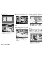
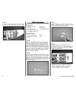
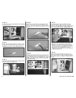
Step 5
Measure and cut a 3
1
/
4
-inch piece of foam from the supplied
foam blocks using scissors.
note
: Use only a few drops of CA so the foam can be
removed if it ever needs to be replaced.
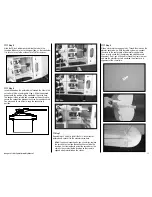
Step 6
Open the bag marked Misc and remove one of the hook and
loop straps. Insert the strap through the slots as shown in
the photo.
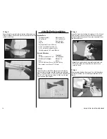
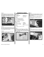
Step 7
There are two different holes in the side of the fuselage that
should match your particular switch. Use a hobby knife to
remove the covering from the appropriate hole. Mount the
switch harness in the side of the fuselage using the hardware
provided with your switch.
note
: Do not cut any switch locations if you are
building the airplane and installing an electric motor.
This will be covered in the Electric Motor Installation
starting on Page 20.
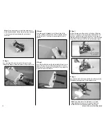
Step 8
Plug the rudder, elevator and throttle servos into the receiver.
The lead from the switch should also be plugged in at this
time. Finally, plug the Y-harness or 6-inch (152mm) servos
extensions for the aileron servos into the receiver.
note
: When using two 6-inch (152mm) extensions,
you will need to use a computer radio with dual aileron
mixing or programmable mixing. Plug the extensions
into the aileron channal and the AUX channel that
corresponds to the opposite aileron channel.
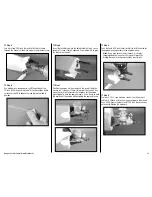
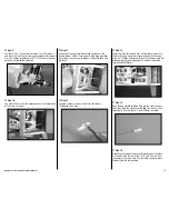
Step 9
Connect the receiver battery to the switch harness. Place
the battery on the foam, then place a piece of foam on the
battery. The receiver mounts on the battery with a piece of
foam between the receiver and hook and loop strap, and
everything is secured by the hook and loop strap installed
in Step 6.
note
: EP version shown without throttle servo
installed. Glow receiver installation is identical.


