15
Hangar 9 Toledo Special Assembly Manual
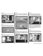
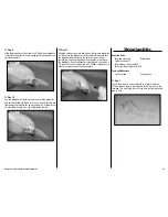
Step 17
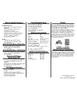
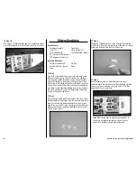
Make a 90-degree bend in the pushrod wire at the mark
made in the previous step. Trim the wire 3/8-inch (9mm)
above the bend. Insert the bend through the hole in the
servo horn and secure the pushrod to the servo horn using a
pushrod keeper.
Step 18
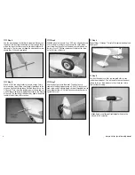
Check the operation of the carburetor and that it can move
from open to closed using the radio system. You may need
to use the end point adjustments in the radio programming
to fine-tune the operation of the throttle.
Step 19
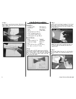
Use medium CA to glue the throttle tube support to the
fuselage side and to the pushrod tube.
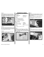
4-Stroke Engine Installation
Required Parts
Fuselage assembly
Motor mount (2)
#8 washer (8)
8-32 lock nut (4)
Clevis
Clevis retainer
Engine
Pushrod tube, 12-inch (305mm)
8-32 x 1-inch machine screw (4)
8-32 x 3/4-inch machine screw (4)
Throttle pushrod, 16
1
/
2
-inch (420mm)
Tools and Adhesives
Ruler
Threadlock
Phillips screwdriver: #2
Felt-tipped pen
Medium grit sandpaper
Medium CA
Drill
Drill bit: 5/32-inch (4mm)
Clamp
Box wrench or nut driver: 11/32-inch
Step 1
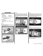
Locate the items to install the engine to your aircraft. You
will find these in the bags marked Pushrod Set and Motor
Mount. Set aside the 1
7
/
8
-inch (48mm) EP standoffs and the
8-32 x 2
1
/
4
-inch machine screws as they are not used when
installing glow engines.
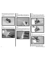
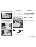
Step 2
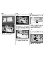
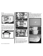
Secure the mounts to the firewall using four 8-32 x 3/4-inch
machine screws and four #8 washers. Make sure to place
a drop of threadlock on each of the screws to prevent them
from vibrating loose.
note
: Blind nuts have been installed for both glow and
EP versions. Make sure to position the mounts at an
angle as shown.
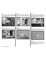
Step 3
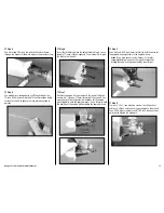
Slide the engine between the mounts. Use a felt-tipped pen
to mark the locations for the throttle pushrod tube on the
firewall.


