background image

20


A

24”

MB3170-GB

Figure 36

Figure 37

Adjusting the balance point 

Figures 36 and 37

The centre of gravity is adjusted by moving 
the wheel to another position on the wheel 
fastening. The wheel fastening has three 
holes. The back holes make the chair most 
safe with regard to tipping, whereas the 
front holes make the chair easier to roll.

20” and 22” driving wheels can be placed 
in any of the three holes, but 24” driving 
wheels can only be placed in the two 
backmost holes.

Always adjust the brakes after you 
have adjusted the balance point!

•  Remove the driving wheel
•  Loosen the wheel casing by unscrewing 

the outward nut (37A) with a 24 mm 
spanner while restraining the inward nut 
with a 24 mm spanner

•  Move the wheel casing to the desired 

hole and screw the nut on again

•  Put the driving wheel back on

20” and 22”

Adjusting the wheelchair

Summary of Contents for Cirrus 4

Page 1: ...Cirrus 4 MB3170 GB User Manual...

Page 2: ...have different needs and wishes whether the chair is to be used simply as a comfort wheelchair or will be driven by the user As the seat height is adjustable it is also very suitable for people who u...

Page 3: ...ion 2 Contents 3 Wheelchair parts 4 Assembly 6 Using the wheelchair 8 Adjusting the wheelchair 17 Positioning belt 24 Safety 25 Safety in cars 27 Maintenance 30 Technical specifications 33 Labelling 3...

Page 4: ...he relevant parts on your wheelchair The equipment on your wheelchair may vary slightly from that shown in Figures 1 and 2 If Cirrus 4 has been set up as a helper guided chair it is equipped with diff...

Page 5: ...5 MB3170 GB Figure 2 Pushing handle Handle for backrest angle Tilt handle Backrest shell Driving wheel Hand rim Anti tip stabiliser Wheelchair parts...

Page 6: ...nd 5 Pull out the bolt 3A Locate the wires between the brackets as shown in Figure 4 Place the bar for the adjustment mechanism into the bracket and replace the bolt Pull out the bolt 4A Place the bar...

Page 7: ...e armrests Fit the armrest as shown in Figure 6 If the locking pin 6A does not lock properly move the back armrest fixing 6B inwards or outwards until the locking pin goes into the locked position Pus...

Page 8: ...button pops out about 5 mm when the wheel bolt is completely in the casing Height adjustable pushing handle Figure 8 The pushing handle can be adjusted by loosening the locking handles 8A at the same...

Page 9: ...the assistant should grip firmly on the pushing handle with one hand and operate the adjustment levers with the other hand An extra adjustment lever for user operated adjustment of the backrest angle...

Page 10: ...le 12A backwards at the same time as taking hold of the strap 12B and pushing or pulling the seat to the desired position Pull the sliding seat to the fully forward position when transferring into and...

Page 11: ...so that the leg support is swung The entire leg support unit with its fixing can be removed see page 18 Figure 16 Full footplate Standard on Cirrus X chairs Figure 16 The full footplate can be split...

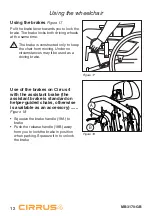
Page 12: ...hair from moving Under no circumstances may it be used as a driving brake Use of the brakes on Cirrus 4 with the assistant brake the assistant brake is standard on helper guided chairs otherwise is av...

Page 13: ...nd Remove the seat cushion Remove the driving wheels Fold down the backrest Folding down the backrest Figure 20 Move the backrest completely forward Pull out the bolts for the pneumatic spring and the...

Page 14: ...ing out or remove the leg supports Tilt the chair forwards Use the sliding seat to move the user as far forwards in the chair as possible see Figure 12 page 9 The user can now be transferred out of or...

Page 15: ...better lifting position they can if necessary lift with one assistant on each side of the chair Negotiating obstacles kerbs Figure 26 When you need to climb kerbs etc if necessary push up the anti ti...

Page 16: ...points Figure27 The lifting points are the pushing handle and the frame Ensure that the locking handles on the pushing handle are well tightened before you lift Do not use the armrests to lift the wh...

Page 17: ...s standard equipped with a clearance down to the base which makes it possible to mount doorsteps etc Adjusting the brakes Figure 29 If small adjustments are needed to the brakes it is sufficient to ad...

Page 18: ...tion The leg support fitting must not be pulled out more than 8 cm Re tighten the screw Legrest angle adjustment Figure 31 The legrests can be adjusted separately Loosen the locking handle 31A Adjust...

Page 19: ...Squeeze in the snap lock 34A in the square profile tubing at the same time as pulling or pushing the calf support to the desired height Depth adjustment Loosen the lock wheel 34B Move the calf support...

Page 20: ...chair easier to roll 20 and 22 driving wheels can be placed in any of the three holes but 24 driving wheels can only be placed in the two backmost holes Always adjust the brakes after you have adjust...

Page 21: ...ey while restraining on the outside with a 10 mm spanner Raise or lower the backrest shell to the desired position Screw the screws back in again and replace the backrest cushion Adjusting the head an...

Page 22: ...ar down that the armrest fouls the driving wheel Screw the screws back in again and fix the armrest to the bracket Loosen the handle 41C and adjust the height at the front Ensure that the handle has l...

Page 23: ...can be adjusted to the following seat widths Figure 42 Model Seat width Cirrus 4 Narrow Cirrus K 34 41 cm Cirrus 4 Wide 41 48 cm Cirrus 4 X Wide 48 55 cm Cirrus 4 X 65 60 67 cm Cirrus 4 X 70 65 72 cm...

Page 24: ...is correctly adapted to the wheelchair user The belt should lie firmly over the hip at an angle of approx 45 from the fixing position on the wheelchair Make sure the belt is clean and that the locking...

Page 25: ...castor wheels changing the backrest height etc this can affect the chair s driving characteristics balance and tipping point Exercise particular care when you start to use the chair again Avoid makin...

Page 26: ...26 MB3170 GB Figure 45 Reflectors Figure 45 Use reflectors when using Cirrus 4 outdoors See Figure 45 for reflector locations Safety...

Page 27: ...argo area or secured in the vehicle during travel The wheelchair can be used as a passenger seat in a car and has been tested in accordance with ISO 7671 19 When the wheelchair is used as a passenger...
Page 28: ...ds when used as a passenger seat in a car WARNING a Where possible the wheelchair should be in a forward facing direction and secured in accordance with the instructions from the manufacturer of the f...
Page 29: ...from the chair and secured in the vehicle during transport so that they don t become loose and cause injury to the user in the event of a collision g Support and positioning equipment must not be reg...

Page 30: ...onditions which may damage the wheelchair The chair should not be used in temperatures below 35 C or over 60 No requirements are specified in connection with humidity and air pressure No other require...

Page 31: ...ure 630 6 3 90 Castor 6 pneumatic tyres 250 2 5 35 Castor 8 pneumatic tyres 250 2 5 36 Tools for service and maintenance of the wheelchair Inspect after six months and then every year Check that the b...
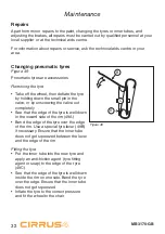
Page 32: ...the valve or by unscrewing the valve out completely See that the edge of the tyre is well down in the inward side of the rim 49A Bend the edge of the tyre over the edge of the rim Use a special tyre...

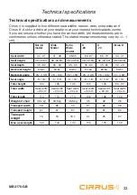
Page 33: ...8 48 55 60 67 65 72 34 41 Seat height 48 42 53 48 42 53 48 42 53 48 42 53 48 42 53 38 38 48 Seat depth 45 60 45 60 45 60 45 60 45 60 32 43 Backrest height 63 67 63 67 60 64 60 64 60 64 53 57 Backrest...

Page 34: ...irrus 4 is suitable for both indoor and outdoor use The chair has been developed for people with reduced muscular strength reduced mobility and reduced stability Handling of waste Waste connected to t...

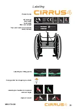
Page 35: ...name CE marking Seat width Seat depth Max user weight Year and month of production Serial number Labelling for lifting points Fixing points for strapping in vehicle Labelling for handles for backrest...

Page 36: ...36 MB3170 GB Accessories...

Page 37: ...t adjustable to 70 80 and 90 Complete calf support Complete footplate Heel cap Amputee support Backrest Tilt adjustment lever on pushing handle Head and neck support various types Adapter for backrest...

Page 38: ...not covered by this guarantee Damage to accessories is not covered by this guarantee Equipment that is not treated with due care or is used in a way that is inconsistent with the guidelines in our use...

Page 39: ...must therefore not be interpreted as an obligation on the part of Handicare Handicare takes no responsibility legal or financial for any errors or inaccuracies which may be found in this user manual...

Page 40: ...B 2013 Handicare Manufactured by Handicare www Handicare com...

Reviews: