background image


1. 

Compressor’s characteristics 

1-1 Multi country (Taiwan, China, USA, England) patented high efficiency 5 to 6 asymmetrical rotor profile. 


1-2 Precise volume control system 

Steps or continuous capacity control system are available. 


1-3 Economizer applications 

Economizer port is a standard accessory for RC2-F series screw compressor. 

Floating type medium pressure (Economizer returned pressure) design, no matter if compressor work at full 

load or partial load condition, always can track the best medium pressure value, it means economizer could 

develop the maximum efficiency during the operation.   


1-4 Applicable with

R-134a, R-407C, R22, R404A, R507A. 


1-5 Resistant to high load condition with long life bearing design 


1-6 PTC temperature thermistor for the protection of 

(1)  High motor coil temperature   

(2)  High discharge temperature   

(3)  High oil temperature (optional) 


1-7 Low vibration and low noise. 


1-8 High efficiency oil separator, low-pressure drop, external connection. 


Summary of Contents for RC2-F Series

Page 1: ...nts table 66 5 Electrical data and design 67 5 1 Motor design 67 5 2 Compressor protection devices 69 5 3 Power supply 69 5 4 Selection of magnetic contactor 71 5 5 Grounding 71 6 Compressors accessor...

Page 2: ...r bearing life compare to competitors These bearings provide strong support to screw rotors especially for the heavy duty application Oil Refrigerant injection port can be utilized when external cooli...

Page 3: ...d pressure design no matter if compressor work at full load or partial load condition always can track the best medium pressure value it means economizer could develop the maximum efficiency during th...

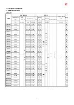
Page 4: ...371 308 35 50 75 100 35 100 71 59 565 RC2 320AF 384 320 25 50 75 100 25 100 72 60 595 RC2 340AF 407 339 35 50 75 100 35 100 77 64 600 RC2 370AF 440 366 35 50 75 100 35 100 84 70 610 RC2 410AF 490 407...

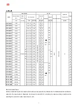
Page 5: ...F 440 366 35 50 75 100 35 100 130 108 640 RC2 410BF 490 407 25 50 75 100 25 100 146 121 380 440 460 480 575 740 RC2 470BF 567 471 25 50 75 100 25 100 170 141 810 RC2 510BF 611 508 35 50 75 100 35 100...

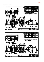
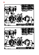
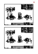
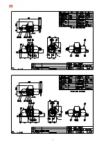
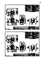
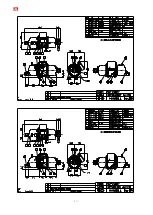
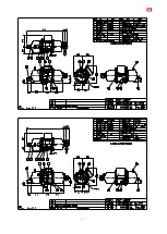
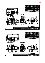
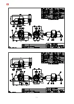
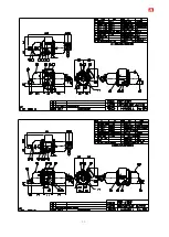
Page 6: ...5 2 2 Compressor outline...

Page 7: ...6...

Page 8: ...7...

Page 9: ...8...

Page 10: ...9...

Page 11: ...10...

Page 12: ...11...

Page 13: ...12...

Page 14: ...13...

Page 15: ...14...

Page 16: ...15...

Page 17: ...16...

Page 18: ...17...

Page 19: ...18...

Page 20: ...19...

Page 21: ...20...

Page 22: ...21...

Page 23: ...22...

Page 24: ...23...

Page 25: ...24...

Page 26: ...25...

Page 27: ...26...

Page 28: ...27 Note For RC2 1020BF RC2 1130BF RC2 1270BF and RC2 1530BF outline drawing please refer to those of RC2 1020AF RC2 1130AF RC2 1270AF and RC2 1530AF...

Page 29: ...d 25 Power bolt 12 Bearing seat cover plate 26 Terminal cover plate 13 Modulation slide valve 27 PTC discharge temperature sensor 14 Slide valve key No Description No Description 1 Compressor casing 1...

Page 30: ...on slide valve 30 Thermostat terminals 15 Slide valve key 31 Motor cable cover plate 16 Discharge bearings 32 PTC discharge temperature sensor No Description No Description 1 Compressor casing 18 Disc...

Page 31: ...ion and then some of the refrigerant gas bypasses from the compression chamber back to the suction end As a result the refrigeration capacity decreases because of the reduction of displacement of refr...

Page 32: ...long time the problem of oil return motor cooling and high discharge temperature and other problem should be considered seriously to prevent inappropriate operation of the compressor which may damage...

Page 33: ...perature control depends on the precision of temperature sensor The timer resolution of control system affects the capacity control s speed Hanbell recommends setting the timer resolution between 0 1...

Page 34: ...iods of time it is important to operate the compressor within these limits to maintain proper compressor life Operating at extra low saturated suction temperature may cause oil management problem and...

Page 35: ...ooling methods 1 Oil cooler 2 Liquid injection to chamber 3 Liquid injection to motor Please refer to Hanbell selection software for calculation and chapter 9 application for design reference 2 The mi...

Page 36: ...ting conditions outside the limits shown 2 6 Compressor design feature 2 6 1 Compressor volume ratio The Volume ratio Vi of the compressor can be defined as the ratio of suction volume of gas divided...

Page 37: ...ftware to get the recommended Vi for different working condition Built in fixed type Vi 2 6 2 Floating type medium pressure for application with economizer Normally a fix type medium pressure compress...

Page 38: ...72 183 550 RC2 430AF 230 233 700 218 243 730 211 230 690 277 273 820 239 233 700 229 243 730 219 230 690 183 183 550 RC2 470AF 248 270 810 236 282 845 227 265 795 300 328 985 259 270 810 248 282 845 2...

Page 39: ...79 292 875 267 305 915 256 283 850 214 250 750 RC2 470BF 310 407 1220 294 428 1285 284 387 1160 372 482 1445 321 407 1220 307 428 1285 294 387 1160 246 323 970 RC2 510BF 336 443 1330 319 463 1390 308...

Page 40: ...08 704 1135 186 428 690 161 350 565 154 329 530 147 322 520 123 273 440 RC2 310AF 163 350 565 155 329 530 149 322 520 360 822 1325 341 763 1230 326 704 1135 197 428 690 170 350 565 163 329 530 156 322...

Page 41: ...177 481 740 424 1260 1940 401 1121 1725 384 1004 1545 232 614 945 200 507 780 192 497 765 184 481 740 153 403 620 RC2 310BF 203 507 780 193 497 765 186 481 740 446 1261 1940 421 1121 1725 403 1004 15...

Page 42: ...weight Make sure that the chains cables ropes or other lifting equipment are properly positioned to avoid possible damage to the compressor or its accessories Keep the compressor in horizontal positi...

Page 43: ...per tube to be the suction and discharge piping tubes Copper tubes are better to minimize the vibration in the piping while the compressor is in operation In case steel tubes are used in piping system...

Page 44: ...before starting make sure to read carefully all the instructions contain inside this manual and make sure that each step is done in accordance with the specification 1 External oil separator 7 Oil lev...

Page 45: ...sion chamber Liquid injection for cooling motor winding Economizer A O Ci Oi Ei Li 1 Check valve 8 To principal return oil port Oi 2 External oil separator 9 To medium pressure Economizer return port...

Page 46: ...45 Item Oil cooler Oil injection into compression chamber Liquid injection into compression chamber Liquid injection for cooling motor winding Economizer B O O O O Ci Oi Ei Li...

Page 47: ...2 External oil separator 12 To medium pressure economizer return port Ei 3 Stop valve 13 Liquid injection to motor winding port Li 4 Oil cooler 14 Liquid injection solenoid valve 5 Oil filter 15 Liqu...

Page 48: ...expansion valve 6 Lubricant flow switch 17 Liquid line filter 7 Oil solenoid valve 18 To medium pressure economizer return port Ei 8 Sight glass 19 Muffler 9 To principal return oil port 20 Strainer 1...

Page 49: ...Strainer 4 Oil cooler 13 Sub cooler 5 Oil filter 14 Expansion valve 6 Lubricant flow switch 15 Liquid injection to motor winding port Li 7 Oil solenoid valve 16 Liquid injection to expansion valve 8 S...

Page 50: ...ubricant circuit 1 External oil separator 7 Oil level switch 2 Oil cooler 8 Oil temperature sensor 3 Oil filter and cartridge 9 Oil heater 4 Lubricant flow switch 10 Manually adjustable flow valve 5 O...

Page 51: ...ompression chamber Liquid injection for cooling motor winding Economizer A O 1 Check valve 8 To principal return oil port Oi 2 External oil separator 9 To medium pressure Economizer return port Ei 3 S...

Page 52: ...2 External oil separator 12 To medium pressure economizer return port Ei 3 Stop valve 13 Liquid injection to motor winding port Li 4 Oil cooler 14 Liquid injection solenoid valve 5 Oil filter 15 Liqui...

Page 53: ...id line filter 3 Stop valve 14 Liquid injection to motor winding port Li 4 Oil cooler 15 Liquid injection solenoid valve 5 Oil filter 16 Liquid injection expansion valve 6 Lubricant flow switch 17 Liq...

Page 54: ...ressure economizer return port Ei 2 External oil separator 11 Muffler 3 Stop valve 12 Strainer 4 Oil cooler 13 Sub cooler 5 Oil filter 14 Expansion valve 6 Lubricant flow switch 15 Liquid injection to...

Page 55: ...ubricant circuit 1 External oil separator 7 Oil level switch 2 Oil cooler 8 Oil temperature sensor 3 Oil filter and cartridge 9 Oil heater 4 Lubricant flow switch 10 Manually adjustable flow valve 5 O...

Page 56: ...ompression chamber Liquid injection for cooling motor winding Economizer A O 1 Check valve 8 To principal return oil port Oi 2 External oil separator 9 To medium pressure Economizer return port Ei 3 S...

Page 57: ...2 External oil separator 12 To medium pressure economizer return port Ei 3 Stop valve 13 Liquid injection to motor winding port Li 4 Oil cooler 14 Liquid injection solenoid valve 5 Oil filter 15 Liqui...

Page 58: ...id line filter 3 Stop valve 14 Liquid injection to motor winding port Li 4 Oil cooler 15 Liquid injection solenoid valve 5 Oil filter 16 Liquid injection expansion valve 6 Lubricant flow switch 17 Liq...

Page 59: ...ressure economizer return port Ei 2 External oil separator 11 Muffler 3 Stop valve 12 Strainer 4 Oil cooler 13 Sub cooler 5 Oil filter 14 Expansion valve 6 Lubricant flow switch 15 Liquid injection to...

Page 60: ...lubricant circuit 1 External oil separator 7 Oil level switch 2 Oil cooler 8 Oil temperature sensor 3 Oil filter and cartridge 9 Oil heater 4 Lubricant flow switch 10 Manually adjustable flow valve 5...

Page 61: ...ompression chamber Liquid injection for cooling motor winding Economizer A O 1 Check valve 7 To principal return oil port Oi 2 External oil separator 8 To medium pressure Economizer return port Ei 3 S...

Page 62: ...2 External oil separator 12 To medium pressure economizer return port Ei 3 Stop valve 13 Liquid injection to motor winding port Li 4 Oil cooler 14 Liquid injection solenoid valve 5 Oil filter 15 Liqui...

Page 63: ...id line filter 3 Stop valve 14 Liquid injection to motor winding port Li 4 Oil cooler 15 Liquid injection solenoid valve 5 Oil filter 16 Liquid injection expansion valve 6 Lubricant flow switch 17 Liq...

Page 64: ...ressure economizer return port Ei 2 External oil separator 11 Muffler 3 Stop valve 12 Strainer 4 Oil cooler 13 Sub cooler 5 Oil filter 14 Expansion valve 6 Lubricant flow switch 15 Liquid injection to...

Page 65: ...also reduce the oil viscosity which might become the root cause of bearing failure in the future The oil viscosity is recommended at 10 s mm 2 at any temperature If the compressor operates under the c...

Page 66: ...ill shut down automatically to prevent the bearing away from getting damage by lacking of lubrication 2 Acidified system due to the moisture will cause the reduction of bearing and motor s life Check...

Page 67: ...NT 40 35 25 30 43 35 T A N mg KOH g 0 01 0 00 0 01 COPPER STRIP 100 3hr 1a 1a 1a MOISTURE ppm 15 20 20 FLOC POINT 75 45 35 DIELETRIC STRENGTH 2 5mm kV 75 50 50 46 6 Applicable oil types R134a R404A R4...

Page 68: ...CS become deductive Around 0 25 sec later MCM MCD are inductive it turns out run connection Y motor connection method is shown in the following motor wiring diagram Full load Amper Starting Current Ti...

Page 69: ...2 580F are available to be fitted with PWS motor for customer s application as an optional accessory Please refer to the follow diagram for the wiring of PWS motor Full load Amper Starting Current Tim...

Page 70: ...andard Discharge temperature protector PTC sensor Cutout 110 Cut in 60 Standard Phase reversal protector INT69 HBY Optional Phase failure protector INT69 HBY Optional Oil level switch Optional Oil fil...

Page 71: ...mended and will probably result in damage to the motor Unbalanced voltages at motor terminals cause phase current unbalance ranging from 6 to 10 times the percent voltage unbalance for a fully loaded...

Page 72: ...rotection should be greater than 50mA for a humid location 25mA is better b Grounding voltage of casing should be no greater than 50V for a humid location the limit is 25V c Grounding resistance shoul...

Page 73: ...valve Liquid injection system solenoid valve stop valve Horizontal check valve External oil separator External oil filter Oil flow switch Economizer Economizer connection stop valve Oil cooler Oil pum...

Page 74: ...Steel pipe Copper pipe RC2 100F 140F 1 1 2 1 5 8 2 2 1 8 RC2 180F 1 1 2 1 5 8 2 2 1 8 RC2 200F 2 2 1 8 2 1 2 2 5 8 RC2 230F 260F RC2 300F 310F RC2 320F 2 1 2 2 5 8 3 3 1 8 RC2 340F 370F 2 1 2 2 5 8 4...

Page 75: ...90 2 103 RC2 340F RC2 370F Discharge Copper 2 1 8 60 110 35 54 3 65 2 5 8 67 77 3 1 8 79 8 90 Steel 2 1 2 77 2 90 Suction Copper 3 1 8 76 145 50 79 8 87 3 5 8 92 4 103 4 1 8 105 1 116 Steel 3 90 2 10...

Page 76: ...RC2 300F 310F RC2 320F 2 1 2 3 RC2 1020F RC2 1130F 4 6 RC2 340F 370F 2 1 2 4 RC2 1270F RC2 1530F 6 8 Dimensions for 1 1 2 4 stop valves Dimensions for 5 stop valve Dia Dimensions unit mm A B C D E F...

Page 77: ...igerant enters the suction port of non working compressor because of head of height potential energy The inner structure of suction check valve is opposite to the inner structure of discharge check va...

Page 78: ...nal oil filter in oil return line before suction port of compressor for safe running of compressor Flow Rate max 50 l m Weight 1 4KG Set Working Pressure 40 bar the weight is not including element Mat...

Page 79: ...mpressor These sensors are connected to an INT69 control module to monitor the motor coil temperature and discharge temperature as well If the temperature in one of the positions monitored exceeds the...

Page 80: ...and phase sequence protection function well please connect L1 L2 and L3 to motor side as figure shown above Motor temperature Motor temperature is constantly measured by a thermistor PTC loop connect...

Page 81: ...rmistor resistance increases above trip level the relay drops out This failure results in a lockout 5 minutes delay for 1st PTC failure 60 minutes delay for 2nd failure lockout for 3rd failure 4 If a...

Page 82: ...erature display setpoint of alarm trip lockout and precisely controlling liquid injection solenoid valve in order to properly protect Hanbell compressor LA 1090 1280 1520 compressor adopts independent...

Page 83: ...ased on Displacement m3 hr Recommended Shell Diameter High level Low level OS40 Vertical 17 9 205 14 OS50 Vertical 22 12 206 270 16 OS65 Vertical 31 18 271 440 18 OS80 Horizontal 33 20 441 705 20 OS10...

Page 84: ...S G 1 PCS 7 Oil level switch 1 PCS 8 Oil heater 150W 150W 150W 150W 150W 300W 300W 9 Oil drain valve 1 4 Flare 10 Oil temp protection option 1 8 NPTF 11 Safety valve option 1 2 1 2 1 2 1 1 1 1 2 1 1...

Page 85: ...84 Horizontal External Oil Separator OS80 Horizontal External Oil Separator OS100 OS125 OS150...

Page 86: ...compressor higher than system temperature and ambient temperature and then it can prevent condensation of refrigerant inside oil sump of compressor which may result in liquid compression in next start...

Page 87: ...0F RC2 230F RC2 260F RC2 300F RC2 310F 25 70 60 25 18 15 mm RC2 340F RC2 370F RC2 410F RC2 430F RC2 470F RC2 510F RC2 550F RC2 580F RC2 620F RC2 710F RC2 790F RC2 830F RC2 930F 35 110 85 30 22 15 mm R...

Page 88: ...ed Keep wire cables away from heat source and sharpened metal Power terminals are fixed firmly and well insulated Terminal screw and block are both required 5 Ruled by the local Electricity Regulation...

Page 89: ...ormal Therefore resonance should be often the cause of vibrations 14 Normally the pressure drop at oil filter should be around 0 to 0 5 bar If the pressure drop is continues rising and reaches 1 bar T...

Page 90: ...y the discharge temperature will start to increase after the stop of Liquid Oil injection Therefore user should observe the working situation for some time to ensure the proper work of Liquid Oil inje...

Page 91: ...mpressor oil separator to avoid gas pads or any drainage of oil into the oil separator during standstill Oil filter Oil filter is usually installed on the oil line User should consider installing a pr...

Page 92: ...opened to balance the pressure differential between high and low pressure side then close itself for the next running With the help of suction check valve and discharge bypass line the reverse runnin...

Page 93: ...built in oil line clogged Check and clean the compressor oil circuit Piston stuck up Change piston or piston ring Oil filter cartridge clogged Clean oil filter replace if needed Too small the high low...

Page 94: ...Loosen internal parts Dismantle the compressor and change the damaged parts Electromagnetic sound of the solenoid valve Check System harmonic vibration caused by improper piping system Check the syst...

Page 95: ...dditional refrigerant Evaporator dirty or iced Defrost or clean coil Clogged liquid line filter drier Replace the cartridge Clogged suction line or compressor suction strainer Clean or change suction...

Page 96: ...7 5 Compressor checking list Please fill out the compressor checking list and send it to Hanbell if any failure of compressor happened Hanbell will reply and suggest the solution to resolve the failu...

Page 97: ...ressure differential between main oil inlet port and suction side is necessary System designer should consider installing the necessary pressure sensors to get the pressure values at main oil inlet po...

Page 98: ...pressure is enough Under such condition the oil pump won t need to work and oil can be supplied from the oil separator to the compressor directly The other function is to prevent back flow of oil when...

Page 99: ...lation problem cannot be solved a secondary oil separator is required to minimize the oil carryover to the system b Piping arrangement In the case of single compressor the suction line design before c...

Page 100: ...line design from suction header to compressors parallel compounding When suction header has to be positioned above compressor level the following design reference has to be considered for safety oper...

Page 101: ...stalling oil separator where the oil level is below the compressor outlet with inclining discharge gas line 1 cm per m This design can ensure no oil flows back to the compressor during standstill Disc...

Page 102: ...below the sight glass of the oil separator and also below the injection point of the compressor In the case of air cooled oil cooler above the oil separator and compressor the oil in the oil cooler wi...

Page 103: ...102 Discharge gas line and oil line design when oil level in oil separator above the compressor level Oil cooling by air cooled version...

Page 104: ...r easier maintenance it is recommended to use a regulation valve ball valve in the oil pipe line to each oil inlet port c Temperature control Temperature control is always critical for a long trouble...

Page 105: ...ed between the liquid line and compressor for cooling down the compression chamber and motor to ensure the continuous and safe running of the compressor The suction superheat should be controlled betw...

Page 106: ...valve should be connected to the high pressure side to counter the internal pressure Please refer to the figure for design reference Liquid injection oil cooling Oil cooler application Compared to liq...

Page 107: ...il bypass line at oil cooler will be needed to ensure a quick warm up d Liquid compression Liquid compression can be classified as oil compression and liquid refrigerant compression For oil compressio...

Page 108: ...ing compressor can have its own working temperature by system design and arrangement Maximize the usage of external oil separator The start up current can be lower at parallel system compare with the...

Page 109: ...108 Parallel compounding with common oil separator and air cooled oil cooler Parallel compounding for different cold space temperatures...

Page 110: ...he compression chamber The power consumption of the compressor increases slightly compare to the additional work that takes place at a better level of efficiency especially at high pressure ratio appl...

Page 111: ...pplied Figure 6 24 shows the system with Economizer sub cooler ECO application by heat exchanger b Economizer by flash tank The liquid sub cooling is achieved by reducing the boiling point pressure in...

Page 112: ...ECO application by flash tank Note When apply the economizer to compressor it is strongly recommended to install a economizer stop valve before the economizer gas return port to operate as a buffer o...

Page 113: ...notice of the high discharge temperature should not exceed 110 f Take notice of high low pressure reading the oil level of the compressor and the noise of running as well If there is any abnormal valu...

Page 114: ...113 8 4 Example of installation Installation of RC2 100 RC2 140 RC2 180 F type compressor Installation of RC2 200 580 RC2 620 F type compressor...

Page 115: ...control system module A Step less capacity control 1 step less 2 25 30 35 B 4 step capacity control 2 25 30 35 3 50 4 75 C Step less step capacity control 1 2 3 4 Suction filter Flange Cable box Powe...

Page 116: ...alve Compression chamber Soleniod valve description 1 Solenoid valve only step less 2 Solenoid valve 25 3 Solenoid valve 50 4 Solenoid valve 75 Capacity control system module A Step less capacity cont...

Page 117: ...66 9 66 9 67 2 67 4 67 5 67 8 68 5 70 0 70 3 70 6 70 9 63 61 1 62 62 9 63 1 63 1 63 4 63 5 63 7 63 9 64 6 66 0 66 3 66 6 66 9 80 67 67 9 68 9 69 2 69 2 69 4 69 6 69 8 70 1 70 8 72 3 72 7 73 0 73 3 100...

Reviews: