background image


User Manual RCx-B-xxxAx-8.09 


Page 5 of 18


www.hanbayinc.com | 1 800 315 4461      

Rev.2021.8                                                                                                                                                                              [email protected] 

Control Signal and Feedback 


Locate the correct connection terminals/wires as shown on the previous page, then connect your input signal 
on positions 1 and 2 (yellow and blue wires) as shown below. Feedback, if applicable is connected to 
position 4 (grey wire). 


1   2   3  4   5   6


P1


4-20 mA Signal source, user 
powered


Actuator


SIGNAL GND


RCx-B-xxxAx  
Internal


RES 
R66


NOTE 1:

 Usually, the actuators are 

shipped for 4-20 mA signal input. 
 
For 1-5 V signal input, remove 250 ohm 
resistor R66. 

The actuator 4-20 mA output is internally supplying the signal current and can drive sufficient voltage for any 
sensing resistor of up to 250 ohms. 
 
The potential of the external GND after the sensing resistor may not be more than +6 VDC / -2 VDC away from 
the power GND of the actuator. 
 
This feedback signal output is only available in RCx-AC-B-xxxAF model actuators. 


External  
4-20 mA 
Sensing 
resistor


NC


NOTE 3:

 DO NOT CONNECT pin 4 

directly or through a multimeter only to 
ground. 
A sensing resistor of 50 ohms or more 
needs to be present. 
Not observing this warning will damage 
the equipment. 


NOTE 2:


Signal Gnd. is NOT 

ISOLATED from Power Gnd. in all 
RCx-AC-B-xxxAB basic models. 
If your signal Gnd. is different from 
Power Gnd. use HANBAY  
RCx-B-xxxAI or RCx-B-xxxAF model 
actuators. 


B   B   B   B 
 4   3    2   1   


Summary of Contents for RC Series

Page 1: ...Explosion Proof Actuators 2 Wiring for Non Explosion Proof actuators 4 Power Supply and Current Draw 4 Control Signal and Feedback 5 Operation 6 DIP switches 6 Controlling the Actuator 6 Changing the...

Page 2: ...ocation should be installed by qualified personnel in accordance with site and local requirements The actuator comes standard with a FNPT thread cable entry See p 14 for location of FNPT housing acces...

Page 3: ...d cable gland are installed connect the wires to the pins on the terminal block as indicated here Pin Function 6 Already Connected to battery board then transformer board serially Connect live wire to...

Page 4: ...moving the actuator draws approx 5 mA AC power is connected to the RED BLACK wires with crimp connectors WM18225 DN WM18230 ND 18 22 AWG Ground is connected on the panhead ground screw circled in yell...

Page 5: ...e actuator 4 20 mA output is internally supplying the signal current and can drive sufficient voltage for any sensing resistor of up to 250 ohms The potential of the external GND after the sensing res...

Page 6: ...IP 6 and 8 are on then the total turns of the actuator would be five 9 Signal loss See p 10 10 11 Seating Torque Set how much torque the actuator exerts on the valve lever during the calibration findi...

Page 7: ...0 0 1 0 0 0 1 2 0 0 1 0 3 0 0 1 1 4 0 1 0 0 5 0 1 0 1 6 0 1 1 0 7 0 1 1 1 8 1 0 0 0 9 1 0 0 1 10 1 0 1 0 11 1 0 1 1 12 1 1 0 0 13 1 1 0 1 14 1 1 1 0 15 1 1 1 1 WARNING Be sure that the number of turns...

Page 8: ...double the power set by DIP 10 and DIP 11 up to 100 power This pull out function is always enabled Speed and Torque Details The maximum speed of the actuator can be set by using the first two positio...

Page 9: ...de torque values by 3 To convert in lbs to Nm divide by 9 RCH AC B xxxAx Actuators Speed Torque DIP 1 DIP 2 Time for 1 turn sec DIP 10 DIP 11 Seating Torque in lbs Operating torque is 100 OFF OFF 90 O...

Page 10: ...ition The default signal position is an absolute actuator position i e not a signal value 3 Re zeroing the actuator and initiating calibration routine The actuator will re zero when the input signal i...

Page 11: ...anually If the valve is moved with the manual override when its power is turned off it will lose its position and it will need to be re zeroed as described in the Signal Loss and Calibration section T...

Page 12: ...onths without power being applied The fail safe actuation can be performed for 30 cycles on the charge available in the battery During normal operation from totally discharged the batteries will take...

Page 13: ...x AC B BxxAx IECEX Standards Editions IEC 60079 0 2017 7th Edition IEC 60079 1 2014 7th Edition Serial number will be engraved on the lid CSA Standards Class I Div 1 Groups B C D T6 Class II Groups E...

Page 14: ...User Manual RCx B xxxAx 8 09 Page 14 of 18 www hanbayinc com 1 800 315 4461 Rev 2021 8 hanbaysales hanbayinc com ACTUATOR DIMENSIONS RCJ RCL RCM AC B xxxAx models...

Page 15: ...User Manual RCx B xxxAx 8 09 Page 15 of 18 www hanbayinc com 1 800 315 4461 Rev 2021 8 hanbaysales hanbayinc com RCH AC B xxxAx models...

Page 16: ...User Manual RCx B xxxAx 8 09 Page 16 of 18 www hanbayinc com 1 800 315 4461 Rev 2021 8 hanbaysales hanbayinc com RCF AC B xxxAx models...

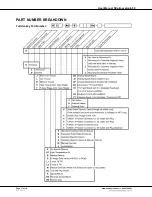
Page 17: ...User Manual RCx B xxxAx 8 09 Page 17 of 18 www hanbayinc com 1 800 315 4461 Rev 2021 8 hanbaysales hanbayinc com PART NUMBER BREAKDOWN Full Hanbay Part Number...

Page 18: ...Part Number Refer to part number breakdown for available options Ex proof Certification Info on ex proof ratings and installation instructions Actuator Serial Number This serial number is unique for...

Reviews: