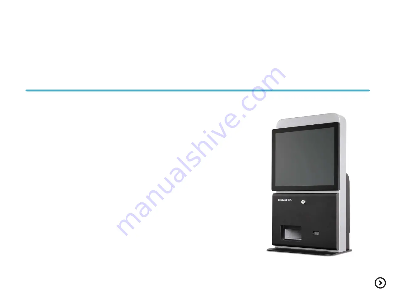
K-170D
User manual
Before use the product,please read this manual carefully.
Safety precations
Page 1: ...K 170D User manual Before use the product please read this manual carefully Safety precations...
Page 2: ...er connection Power on off 10 11 12 6 6 7 8 9 Adapter replacement System adapter Printer adapter Printer replacement Barcode scanner replacement System AS MainPCB 14 Bios setting 19 14 15 16 17 18 Ext...
Page 3: ...oval and any circuit damage Please use the product in the wide area having ventilation Please avoid direct sun ray humid area hot and frequent temperature change area Do not connect the product with h...
Page 4: ...cation can be changed without any notice as purpose of improving quality K 170D is tested fully to certify it s quality and durablity based on Hanasis excellent technology K 170D is applied gorgeous a...
Page 5: ...24 24 BIT Serial 5 EA DSUB 9p x 2EA RJ 45 x 3EA Graphic Touch screen Dispaly 17 TFT LCD LVDS 1280 X 1024 24 BIT Luminance 250 cd Backlight LED Chipset System on chip SoC Touch type 17 Bezel type 5 Wir...
Page 6: ...ame Function Installation Usage Extension Bios Configuration Front Rear Exterior design Parts name and Product Function Exterior design Product Inside Product I O Product Iabel Lock Door Scanner Recei...
Page 7: ...n Installation Usage Extension Bios Configuration Exterior design Product Inside Product I O Product Inside Parts name and Product Function Please open the door after unlocking the locker by the key k...
Page 8: ...basic setting 5 LAN RJ 45 Internet connection or Hub 6 USB2 0 USB Keyboard USB Mouse 7 8 9 10 11 12 13 USB3 0 USB 2 0 device USB 3 0 Supportive device Interface Parts name and Product Function Front R...
Page 9: ...ease check the serial number attached inside the front door Model K 170D Code KK16P BSNN4NSNN01 Rating DC24V 4A 96W Serial No This device complies with Part 15 of the FCC Rules Operation is subject to...
Page 10: ...appen any falling accident Stand installation and Precautions Stand installation stand is optional item Exterior Put the base on the floor then assemble stand body on it Fix the stand and body by 4 sc...
Page 11: ...se put stand cover then fix it with 1 screw Please beware of not to be disturbed the cable Please push the power button located inside the front door then run the system Stand body Inner cable arrange...
Page 12: ...lease push the power switch until power switch power light is turned on Before turning off the system save your files After clicking windows starting button then press the system off button While the...
Page 13: ...going through the front door Please watch out to happen printing jam on the printer head a b Contents Introduction Printer paper replacement Usage Extension Installation Bios Configuration Printer pap...
Page 14: ...System cover is heavy please beware of falling accident is not happened Unscrew 6 screws on the top of the body then disassemble the system cover Please check cable is not disturbed Please unplug adap...
Page 15: ...cting other power adapter After replacing the new adapter please watch out cable is not disturbed from other environmental factor Please open the door After unscrewing 2 x screws disassemble printer c...
Page 16: ...ter 2 Contents Introduction Adaptor replacement Printer replacement Usage Extension Installation Bios Configuration After replacing the new adapter please watch out cable is not disturbed from other e...
Page 17: ...age Extension Installation Bios Configuration After replacing the new adapter please watch out cable is not disturbed from other environmental factor Barcode scanner replacement Product extension 17 O...
Page 18: ...tion Adaptor replacement Printer replacement Barcode scanner eplacement System AS Usage Extension Installation Bios Configuration 1 While reassembly goes on beware of losing the screws After unscrewin...
Page 19: ...e text Press DEL to enter setup please press Delete button 19 Bios Main Feature Advanced Chipset Aptio Setup Utility Copyright C 2016 American Megatrends Inc Boot Security Save Exit BIOS Information P...
Page 20: ...SB HDMI LVDS 2CH 24BIT PS8625 DDR3L 1333MHz AUDIO ALC662 AMI BIOS ROM COIN BAT LED BUTTON COM 1 5 AUDIO AMP PWR PART VCCM DP SPI BUS BACK UP LPS SATA II Intel Celeron BAY TRAIL USB2 0 X 6ea HUB USB2 0...
Page 21: ...5 16 11 13 12 7 5 6 4 3 2 1 10 9 8 1 Touch Panel Controller Pin Header 2 FAN System Connector 3 AT ATX Mode Jumper 4 Reset Connector 5 USB Pin Header 6 DDR 3 SO DIMM Socket 7 USB2 0 Connector 8 Power...
Page 22: ...ontents Introduction Usage Extension Installation Bios Configuration System composition Main board composition Main Jumper setting I O Pin map Main board composition 22 22 Primary chipset and connecto...
Page 23: ...l Port Configuration Serial Port 1 Configuration Main Advanced Topstar Chipset Aptio Setup Utility Copyright C 2 Boot Enabled Serial Port Serial Port 2 Configuration Auto Change Settings Device Settin...
Page 24: ...n Main Jumper setting I O Pin map I O Pin map 24 COM 1 2 3 4 MSR HDMI LAN USB DC IN DC OUT COM 3 4 port RJ 45 COM 1 2 Serial port DSUB 9 Pin 8 8 8 No Signal Description 1 2 3 4 5 6 7 8 N C DSR TXD RXD...
Page 25: ...VUSB 5 0V TXD RXD GND MSR port RJ 45 COM5 USB7 8 8 8 8 1 HDMI port No Signal Description 1 2 3 4 5 6 7 8 9 TMDS Data2 TMDS Data2 Shield TMDS Data2 TMDS Data1 TMDS Data1 Shield TMDS Data1 TMDS Data0 TM...
Page 26: ...al Description 1 2 3 4 5 6 7 8 MD0 MD0 MD1 MD1 MD2 MD2 MD3 MD3 LAN port RJ 45 with LED 8 8 8 8 1 USB 2 0 port TYPE A No Signal Description 1 2 3 4 VUSB 5 0V D D GND 1 4 USB 3 0 port TYPE A No Signal D...
Page 27: ...tion System composition Main board composition Main Jumper setting I O Pin map I O Pin map 27 DC OUT JACK No Signal Description 1 2 3 12V GND GND DC IN Power DIN 4 No Signal Description 1 2 3 4 12V GN...
Page 28: ...http www hanasis com 17 Saneop ro 155beon gil Gwonseon gu Suwon si Gyeonggi do 16648 KOREA Direct 82 70 4732 5264 Fax 82 31 297 4381 Email smkim hanasis com...