Copperhead52
in
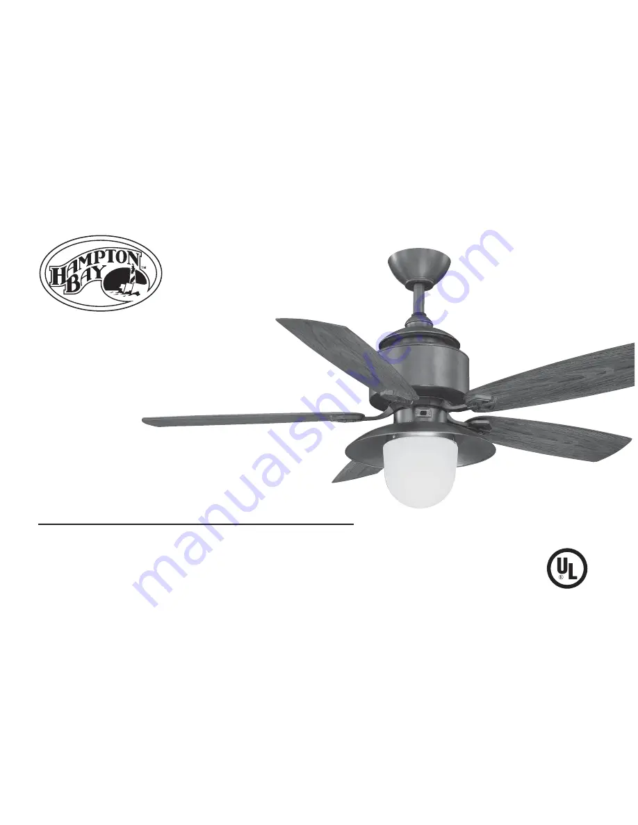
Ceiling Fan
Owner’s Manual
CopperheadVentilador de Techo de 1,32
m
Manual del Propietario
184 860
Page 1: ...Copperhead 52 in Ceiling Fan Owner s Manual Copperhead Ventilador de Techo de 1 32 m Manual del Propietario 184 860 ...
Page 2: ...d with the highest standards of safety and quality The finish of this fan is weather resistant but over time will naturally weather and fade Table of Contents Safety Rules 1 Unpacking Your Fan 2 Installing Your Fan 3 Installing the Light Kit 12 Operating Your Transmitter 13 Care of Your Fan 14 Troubleshooting 14 Specifications 15 Warranty Information 16 184 860 792145353171 219032 ...
Page 3: ...ades To avoid personal injury or damage to the fan and other items be cautious when working around or cleaning the fan Do not use water or detergents when cleaning the fan or fan blades A dry dust cloth or lightly dampened cloth will be suitable for most cleaning After making electrical connections spliced conductors should be turned upward and pushed carefully up into outlet box The wires should ...
Page 4: ... plate Light kit Glass shade 13 Watt compact fluorescent bulb Receiver with 6 wire nuts Wall transmitter incl 2 mounting screws and 3 wire nuts Wall plate w 2 mounting screws 7 8 9 10 11 12 13a 13b Blade Attachment Hardware 16 Screws with Rubber Washers Electrical Hardware 3 Plastic Wire Nuts Balancing Kit A B C WARNING DO NOT INSTALL OR USE FAN IF ANY PART IS DAMAGED OR MISSING CALL TOLL FREE 1 8...
Page 5: ...G SCREWS PROVIDED WITH THE OULET BOX OUTLET BOX COMMONLY USED FOR THE SUPPORT OF LIGHTING FIXTURE MAY NOT BE ACCEPTABLE FOR FAN SUPPORT AND MAY NEED TO BE REPLACED CONSULT A QUALIFIED ELECTRICIAN IF IN DOUBT Outlet Box Outlet Box Outlet Box Figure 2 Figure 1 Note You may need a longer downrod to maintain proper blade clearance when installing on a steep sloped ceiling The maximum angle allowable i...
Page 6: ...et a half turn from the screw head and turning the canopy counter clockwise Figure 5 Remove the clevis pin cotter pin and set screws from the top of the motor assembly Figure 6 NOTE If a longer downrod is needed take out the screw located in the hanger ball lower the hanger ball and remove the pin remove all 3 pieces from the downrod and assemble them onto the new longer downrod before proceeding ...
Page 7: ...vided with your outlet box Figure 7 Security tighten the two mounting screws Carefully lift the fan assembly up to the ceiling mounting bracket and seat the hanger ball in the mounting bracket socket Make sure the tab on the mounting bracket socket is properly seated in the groove in the hanger ball Figure 8 This will help to balance the ceiling fan 1 2 3 4 WARNING THE TAB IN THE RING MUST REST IN...
Page 8: ...wire connecting nuts provided Figure 12 If your outlet box has a ground wire green or bare copper connect it to the fan ground wires otherwise connect the hanging bracket ground wire to the mounting bracket Secure the wire connection with a plastic wire connecting nut provided After connecting the wires spread them apart so that the green and white wires are on one side of the outlet box and black...
Page 9: ...K BLUE WHITE BLACK BLACK Black Ground Green Black Black Black BLACK BLACK BLUE GROUND GREEN BLUE WHITE WHITE BLACK BLUE WHITE WHITE WHITE GREEN WHITE INPUT AC120V AC SUPPLY Outlet Box Ground Conductor Green Ground Lead Ground to Downrod Wall Control ...
Page 10: ...tions as shown in Figure 13 If your outlet box has a ground wire green or bare copper connect the wall transmitter s ground wire to it otherwise connect the wall transmitter s ground wire directly to one of the screws from the outlet box Fig 14 Carefully tuck the wire connections inside the junction box Secure the wall transmitter with the two screws provided Attach the wall plate over the wall tr...
Page 11: ...tabs on the motor housing then tighten the two screws and washers already installed in the blade arms Figure 18 1 2 3 CAUTION MOTOR IS SHIPPED WITH RUBBER PACKING MOUNTS TO PREVENT MOVEMENT DURING TRANSPORTATION REMOVE 5 RUBBER PACKING MOUNTS FROM FAN MOTOR ASSEM BLY AND DISCARD PRIOR TO ATTACHING BLADE ARMS FIG 16 WARNING TO REDUCE THE RISK OF PERSONAL INJURY DO NOT BEND THE BLADE ARMS WHILE INST...
Page 12: ... from a point on the center of each blade to the point on the ceiling Measure this distance as shown in Figure 19 Rotate the fan until the next blade is positioned for measurement Repeat for each blade Measurements deviation should be within 1 8 Run the fan for 10 Minutes Use the enclosed Blade Balancing Kit if the blade wobble is still noticeable 1 2 3 The following procedure should correct most ...
Page 13: ...ection of the key holes Secure by tightening the 2 screws previously loosened and the one previously removed Fig 20 Carefully push all wires back into the switch housing then install the mounting plate onto the switch housing with 3 screws provided Be sure to tighten all screws Fig 21 1 2 3 4 Figure 21 Figure 20 CAUTION BEFORE STARTING INSTALLATION DISCON NECT THE POWER BY TURNING OFF THE CIRCUIT ...
Page 14: ...s Fig 22 Install 13 Watt compact fluorescent bulb included Raise glass shade up against the light kit and secure it to fan by turning glass clockwise until snug DO NOT OVERTIGHTEN Fig 22 Restore power and your light kit is ready for operation 1 2 3 4 5 NOTE LIGHT BULBS HAVE NO WARRANTY CAN BE PURCHASED AT ANY HOME DEPOT STORE NOTE BEFORE STARTING INSTALLATION DISCON NECT THE POWER BY TURNING OFF T...
Page 15: ...rection A downward air flow creates a cooling effect Fig 24 This allows you to set your air conditioner on a higher setting without affecting your comfort Cool weather Clockwise direction An upward airflow moves warm air off the ceiling area Fig 25 This allows you to set your heating unit on a lower setting without affecting your comfort NOTE WAIT FOR FAN TO STOP BEFORE CHANGING THE SETTING OF THE...
Page 16: ...3 4 Here are some suggestions to help you maintain your fan Check main and branch circuit fuses or breakers Check line wire connections to the fan and switch wire connections in the switch housing Check to make sure the dip switches from the transmitter and receiver are set to the same frequency Make sure all motor housing screws are snug Make sure the screws that attach the fan blade bracket to t...
Page 17: ...TS AMPS WATTS RPM CFM N W G W C F 52 120 10 56 kgs 23 28 lbs 12 20 kgs 26 9 lbs 2 36 LOW MED HIGH 0 27 0 43 0 45 15 37 54 65 115 145 2076 3720 4878 These are approximate measures They do not include Amps and Wattage used by the light kit ...
Page 18: ...ormal and should not be considered a defect Servicing performed by unauthorized persons shall render the warranty invalid There is no other express warranty Hampton Bay hereby disclaims any and all warranties including but not limited to Those of merchantability and fitness for a particular purpose to the extent permitted by law The duration of any implied warranty which cannot be disclaimed is li...