


Installation and Service Manual
Overhaul
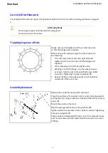
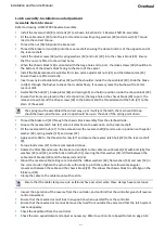
Fit the nozzle housing to the tailpipe
Apply Loctite 243 to studs [26] fitted to the tailpipe of the jet unit. Refer to drawing: HJ21201000 Base
Jet Assembly.
Refit the nozzle insert into the nozzle housing.
Refit the nozzle assembly complete, onto the studs [26], with the nozzle fitted for the correct orientation
(nozzle up or nozzle down).
Secure the nozzle assembly to the tailpipe with spring washers [28] and nuts [27]. Torque load to the
correct torque.
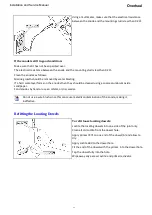
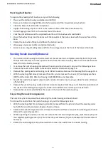
Fit the steering shaft
Lightly grease the steering crank [4] and fit into the steering crank bush [15] in the nozzle boss.
Ensure that the steering crank [4] is correctly orientated to suit the nozzle trim (nozzle up or nozzle
down).
Lightly grease the steering shaft [1] and from inside the vessel, slide the steering shaft rearwards into
position through the forward and aft steering bushes [3]. Take care not to dislodge o-ring [2] fitted to the
forward steering bush.
From outside the vessel, pull the steering shaft rearwards and pass the end of the steering shaft through
the steering crank [4] that has been fitted into the steering bush [15].
From the port side of the jet unit, fit the cotter [5] through the hole in the steering crank to secure the
steering crank to the end of the steering shaft. Secure with washer special [6], spring washer [8] and nut
[7]. Tighten to the recommended torque. Refer to section: Tightening Torques on page 10-28.
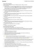
Operate the steering arm [17] and ensure that there is freedom of movement.
Remount the steering cable and check the full steering function.
After re-assembly of the steering shaft, it is essential that the adjustment of the steering
tiller stop is checked. The clearance between the nozzle and the nozzle housing should be
the same in both directions. Adjust the tiller stop by loosening the securing nuts and sliding
the tiller stop sideways as required. Refer to drawing: HJ21206000 Steering Assembly.
Re-tighten the securing nuts to the recommended torque.
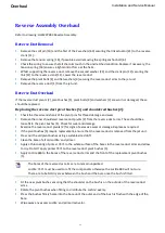
Re-attach the reverse latch brake rod end [26] to the cable mount [20].
Refit brake rod bush [33], flat washer [31], flat washer [32] and bolt [36]. Torque load to the
recommended torque.
Remount the cable and cable clamp and tighten the cable clamp screws and secure with Loctite.
Refit the splash guard [58] to studs [59] and secure with spring washers [19] and nuts [17].
Refit the reverse duct. Refer to section: Reverse Assembly Refitting on page 9-9.
Check all steering and reverse functions for full operational movement.
9-17
Summary of Contents for HJ212
Page 1: ...HJ212 Installation and Service Manual R3A3 Jet unit Manual ...
Page 20: ...Product Description Installation and Service Manual 2 6 ...
Page 56: ...Commissioning Installation and Service Manual 6 4 ...
Page 62: ...Fault Finding Installation and Service Manual 7 6 ...
Page 82: ...Maintenance Installation and Service Manual 8 20 ...
Page 137: ...Installation and Service Manual Appendix Notes 10 21 ...
Page 141: ...Installation and Service Manual Appendix Notes 10 25 ...
Page 164: ...Appendix Installation and Service Manual 10 48 ...
Page 166: ......
Page 169: ......
Page 171: ......
Page 172: ......
Page 175: ......
Page 176: ......
Page 177: ......
Page 178: ......
Page 181: ......
Page 185: ......
Page 186: ......
Page 188: ......
Page 195: ......
Page 196: ......
Page 197: ...Notes ...