background image


Installation and Service Manual 

Appendix 

Ahead, Zero Speed and Astern Controls 

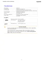
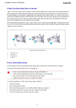
"Astern" and "zero speed" are achieved by re-directing the jetstream. If the reverse duct is lowered fully, all 

of the jetstream is re-directed back under the vessel giving "maximum astern thrust". If the reverse duct is 

lowered partially, the jetstream is split giving some ahead and some astern thrust. At a certain reverse duct 

position the ahead and astern thrusts will be equal so the vessel will not move ahead or astern regardless of 

the throttle opening. This is the "zero speed" position (this term should not be confused with the neutral 

position of a gearbox when the driveline stops rotating). 
When operating the Hamilton reverse control, the jet unit is always rotating regardless of the position of the 

reverse duct. Any intermediate position between ahead and astern can be selected to give infinitely variable 

speeds when manoeuvring. 


Figure 15:


Reverse Duct Positions 

Maximum ahead 

Zero speed 

Maximum astern 

Jet stream 


Power Assisted Slowdown 

A fast slowdown can be achieved by quickly lowering the reverse duct while the vessel is at speed. 
This procedure should only be used in an emergency. 


Power assisted slowdown produces very rapid deceleration. 


Power assisted slowdown should be used with care by new operators. 


Do not use full helm control until the vessel has slowed. 


Select zero speed as soon as the vessel has slowed. 


For normal operation to "brake" the vessels forward motion: 


Close the throttle. 


Select zero speed or astern. 


Open the throttle, gently at first until the desired braking is achieved. 


Close the throttle as soon as the vessel has slowed to a standstill. 


Do not use full steering until the vessel has slowed. 


10-39 

Summary of Contents for HJ212

Page 1: ...HJ212 Installation and Service Manual R3A3 Jet unit Manual ...

Page 2: ... means electronic electrostatic magnetic tape mechanical photocopying recording or otherwise without permission in writing from C W F Hamilton Co Ltd Due to our policy of continuous development specifications in this document are subject to change without notice or obligation Jet or control type HJ212 Part number 089212 Revision R3 01 01 14 Amendment A3 03 02 15 ...

Page 3: ...________________________________3 4 Requirements of the Driveline _________________________________________3 4 H Bar Drive Lines____________________________________________________3 4 Engineering Checks__________________________________________________3 5 Driveline Options ___________________________________________________3 5 Universal Driveshaft Alignment_________________________________________...

Page 4: ...____________________________________4 3 Corrosion Monitor ________________________________________________________4 4 Trim Tabs and Other Submerged Fittings ______________________________________4 4 Earth Connections for Electronic Equipment ___________________________________4 4 Anodes _________________________________________________________________4 5 Jet Unit Anodes____________________________...

Page 5: ..._______5 10 Optional Impeller Installation_________________________________________5 10 Installation of Control Equipment ___________________________________________5 10 Reverse Latch Assembly _____________________________________________5 11 Reverse Cable _____________________________________________________5 11 Zero Speed Detent _________________________________________________5 12 Steering Inst...

Page 6: ...rom the jet unit ______________________________________7 3 Excessive scouring of the shaft sleeve ___________________________________7 3 Reverse System Faults _____________________________________________________7 4 Steering System Faults_____________________________________________________7 5 Steering nozzle slow to respond _______________________________________7 5 Steering jamming _____________...

Page 7: ...____________8 14 Tailpipe nozzle and nozzle housing____________________________________8 14 Jet unit paintwork _________________________________________________8 14 Excessive wear ____________________________________________________8 15 Control System __________________________________________________________8 15 Checking the steering system_________________________________________8 15 Checking th...

Page 8: ...__________________________________________________9 22 Impeller Checking for wear _________________________________________9 22 Marine water bearing Checking for wear ______________________________9 22 Tailpipe Area Dismantling _________________________________________________9 23 Tailpipe Marine Bearing and Wear Ring Inspection_____________________________9 23 Wear Ring Removal and Replacement __...

Page 9: ..._______________________________10 12 Installation Checks ______________________________________________________10 14 Jet Unit Mounting_________________________________________________10 14 Jet Unit General __________________________________________________10 15 Jet Systems Steering _______________________________________________10 16 Drive Shaft_____________________________________________________...

Page 10: ...tarting Up ______________________________________________________10 38 Ahead Zero Speed and Astern Controls _______________________________10 39 Power Assisted Slowdown __________________________________________10 39 Steering _________________________________________________________10 40 Manoeuvring and Docking __________________________________________10 41 Cruising ______________________________...

Page 11: ...s shown to the satisfaction of Hamilton Jet to be defective in material or workmanship during the warranty period Hamilton Jet will supply parts required for warranty repairs free of charge and pay reasonable authorised labour costs To the extent permitted by law this warranty sets out the original purchaser s exclusive remedies with respect to the product covered by this warranty In the event tha...

Page 12: ... Product Manual and a Jet Mainshaft critical speed check carried out to Hamilton Jet s written satisfaction Warranty does not cover or provide payment or reimbursement for the following Any repairs or alterations carried out with the use of parts or accessories not manufactured by Hamilton Jet or its authorised representatives Items incorporated in any Hamilton Jet product other than by Hamilton J...

Page 13: ... Department C W F Hamilton Co Ltd PO Box 709 Christchurch New Zealand Fax 64 3 348 6969 Email marketing hamjet co nz Hamilton Jet encourages the distributor to take responsibility for ensuring the purchaser and the distributor complete this form at the time of sale and return it to Hamilton Jet Please complete one form per vessel only Jet Model Serial Number s Delivery Date Commissioning In servic...

Page 14: ...cated throughout this manual as shown below Caution A caution is an operation or maintenance procedure practice condition or statement which if not strictly observed could result in damage to or destruction of equipment or loss of mission effectiveness This is indicated throughout this manual as shown below Note A note contains additional information that will help clarify a procedure This is indi...

Page 15: ...ability Conventional propeller powered craft have several shortcomings such as vibration higher engine loading and susceptibility to damage from water borne debris Modern waterjet powered vessels offer many advantages High efficiency Rapid acceleration Shallow draft Manoeuvrability Smooth quiet operation Lower maintenance Longer engine life Simplified installation No protrusions under the water Sa...

Page 16: ...table for vessels typically up to 65m in length and are generally driven by high speed diesel engines via a reduction gearbox Mounted partly inboard at the stern of the vessel the Hamilton waterjet consists of a totally integrated jet mounted hydraulic steering reverse and control system package Water is drawn into the waterjet through an intake screen at the base of the intake which is mounted fl...

Page 17: ...ned with the option of a flexible close coupling arrangement combined with an engine mount This allows the engine to be moved as far aft as possible in the boat simplifying the driveline arrangement and providing a low noise torsionally flexible coupling Impeller Mixed flow type capable of pumping large volumes of water at relatively low pressures Permits high propulsive coefficients to be achieve...

Page 18: ...uct has a latch mechanism which locks the reverse duct in position The hand controller automatically releases the brake when operated The reverse duct cannot be moved by hand from outside the boat nor by the pressure of the water The latch has been factory set and should not require adjustment during installation Screen rake May be fitted as an optional extra The screen rake is a hand operated rak...

Page 19: ...roduct Description Figure 2 Figure 1 HJ212 Main Components 1 Intake 7 Reverse duct 2 Intake block 8 Transom plate 3 Inspection hatch 9 Anode 4 Reverse assembly 10 Intake screen hidden 5 Steering shaft 11 Hatch extension 6 Tail pipe 2 5 ...

Page 20: ...Product Description Installation and Service Manual 2 6 ...

Page 21: ...recommended Mount multiple jet units as close to the keel line as possible staggering the engines can allow closer centres Planing strakes keelsons plank keels and any other hull appendages that may create turbulent water flow into the jet unit s must not be fitted in front of or adjacent to the jet unit intakes Refer to figure Mono hull design on page 3 2 For speeds over 30knots monohedron consta...

Page 22: ...rimaran hulls Air can become trapped between the hulls in these types of vessels and care must be taken to ensure that this trapped air does not enter the jet unit intake s This can be avoided if the hulls are deep in relation to the air tunnels so that the jet units sit well down in the water When in the ahead up position the reverse duct must not project beyond the sidewalls of a catamaran or tr...

Page 23: ... thrust Trim tabs therefore must not be mounted beside the jet unit Trim tabs may be mounted under the jet unit with any control equipment mounted on either side of the jet unit The following diagram shows the maximum size and position of the trim tab that may be located under the jet unit Contact Hamilton Jet if further details are required Figure 5 Allowable Trim Tab Location 1 Maximum size of t...

Page 24: ... use e g tourist boats operating in narrow shallow rivers the H bar type drive shaft or companion flange plus Cardan shaft must be used This is to isolate the jet unit from possible high engine inertia forces associated with extreme manoeuvres or groundings Due to certain engine components fouling on the jet unit intake the 454 Chev Mercruiser engine cannot be mated to the HJ212 jet unit using a C...

Page 25: ... adaptor plate or alternatively a suitable torsionally flexible flywheel coupling TFFC can be used between the universal driveshaft and the engine flywheel The TFFC must be of the type with a support bearing to support the universal driveshaft Vulcan Centa and Kusel have suitable couplings for use with universal driveshafts Use of a TFFC is more appropriate for diesel engines and may be stipulated...

Page 26: ...flange 4 Engine gearbox axis 2 Engine coupling flange L Axial distance between the universal driveshaft yokes 3 Jet mainshaft axis Q Offset θ1 and θ2 must be equal Offset L x Tanθ JetCoupling FlangeDetails Refer to drawing HJ21202005 Close Coupling Kit Drivelines forDieselEngines A diesel engine installation will require the engine to be separately mounted from the jet with a torsionally flexible ...

Page 27: ... flexible coupling manufacturer The moment of inertia data for the jet unit is provided so that a torsional vibration analysis can be done Mainshaft Dimensions Figure 8 Mainshaft Dimensions 1 Mainshaft 2 Coupling 3 Impeller 4 Thrust bearing 5 Marine bearing CoG Impeller centre of gravity HJ212 mainshaft dimensions D1 120 D4 55 D2 475 D5 500 D3 160 D6 55 Item Type Mass kg Polar Mol kg m 1 Mainshaft...

Page 28: ...nit mainshaft is inclined at an angle of 5 to the intake base and the port and starboard jets are mounted at the hull deadrise angle then the jet mainshafts are no longer parallel to the keel line in plan The following table lists the angle deviation of the jet unit mainshaft when the jet base is mounted parallel to the keel line Figure 9 Jet Mainshaft Alignment A Plan view 3 Transom B Section thr...

Page 29: ... used The jet unit water offtake can be used for a deck cleaning hose but the pressure is not high enough to be used for a fire hose If a gearbox or clutch is fitted to the engine a conventional hull water pick up and engine raw water pump must be used Make sure that the engine cooling water pick up is not directly ahead of the jet unit intake but well to the side to avoid turbulent water flow int...

Page 30: ...om the jet unit directly to the hull Flexible engine mounts will reduce vibration and noise but must be used in conjunction with a driveshaft system which does not cause radial or side loads at the jet unit coupling as the engine moves H bar drive lines In vessels designed for higher operational hours and severe use e g tourist boats operating in narrow shallow rivers the H bar type drive shaft or...

Page 31: ...of the full throttle RPM achieved when driving the jet unit so that there is no chance of the governor reducing power and performance at full throttle To check select neutral and open the throttle fully Measure RPM using a calibrated hand tachometer If no gearbox is fitted then disconnect the driveline at the engine flywheel and check RPM Example If the maximum RPM for driving the jet unit is 2800...

Page 32: ...be run dry for short periods of time Standard rubber marine bearings cannot be run dry Scopeofuse Because there is no cooling for a dry run system the water seal and the marine bearing will heat up rapidly when the vessel in not in the water Note the following limits to ensure adequate component life Maximum dry run time 3 minutes Maximum dry run engine speed 1000rpm Minimum time between dry runs ...

Page 33: ... Equipment 4 4 Anodes 4 4 Anti Fouling Paint 4 5 Anti Seize Compound 4 5 Impressed Current Protection 4 6 Steel Hulls and Carbon Fibre Reinforced F R P Hulls 4 6 General Refer to drawing 85114 Earth Bonding System Refer to drawing HM00013001 Corrosion Monitor Prevention of Corrosion Vessels using Hamilton jet units must be bonded and wired as described in this section ElectricalWiringSystem The gu...

Page 34: ...h both AC and DC circuits must for safety reasons use a separate earth wire for the AC system If a vessel with bonded aluminium jets is connected to a dock supply without the protection of an isolation transformer or a galvanic isolator the dock potentials through the earth wire will cause the aluminium to corrode This will happen at a much greater rate than that experienced in normal sea water re...

Page 35: ...ould not be connected directly to the jet unit as galvanic corrosion will occur The copper bonding strip should be connected to the jet unit via a stainless steel terminal connector The bonding wire or strip which runs the length of the hull should be kept clear of bilge water The main function of the bonding system is to provide a path to battery negative for stray currents An exception exists fo...

Page 36: ...ct the jet corrosion protection Earth Connections for Electronic Equipment Radios radar and other transmitting equipment should not use the jet unit for an earth plate Be guided by the installation instructions for the equipment but in general these systems should be electrically insulated from the jet unit except that both the earth plate and the metal casings of the transmitting equipment should...

Page 37: ...ce This condition occurs mainly in fresh water Test for continuity between the anode and the jet unit using a multimeter set to ohms If the anode has to be scraped with a knife to get a conductive reading the anode is oxidized and must be replaced Sanding the anode surface provides a temporary solution but will eventually re oxidize JetUnit Anodes Anodes are fitted to the reverse duct steering noz...

Page 38: ...auxiliary equipment installation be guided by your electrician Do not earth electrical equipment to the jet unit but to a separate earth CheckingtheInsulation The insulation between the jet unit s and the steel hull should be regularly checked With the vessel out of the water Rinse the sea salt from the jet unit hull area using fresh water The resistance between the jet unit s and the hull should ...

Page 39: ...this area is in accordance with hull design criteria and any classification society or other marine authority involved GRPHullintakeblock An LM6 grade aluminium intake block is supplied ready to mould and bolt into the bottom of the hull For carbon fibre reinforced hulls Use non conductive reinforcing fibre at the intake block and transom plate to electrically isolate the jet unit from the hull El...

Page 40: ...ue Refer to section Tightening Torques on page 10 28 Make sure that the contours between the hull and the intake block at the front and rear are smooth to within 1mm For aluminium hulls To assist with the correct alignment of the intake block the centreline is marked fore and aft The intake block is butt welded flush with the underside of the hull bottom as shown in the installation drawing The pr...

Page 41: ...starboard or centre mounting Make sure that each jet is installed in the correct position as shown on the installation drawing Do not unpack the jet unit until it is required for installation This will prevent mechanical damage and entry of foreign matter into the jet Unpack carefully to prevent damage and loss of small items Preparation After mounting the intake block and making the transom hole ...

Page 42: ...ne square with the intake flange Make small locating dimples in the transom by drilling through the holes in the transom plate Slide the transom plate off the intake Drill 8 5mm diameter holes through the transom using the dimples to locate Remove all burrs Liberally apply marine sealant 7 supplied to the transom plate contact area on the hull and also the joint face of the transom plate and the h...

Page 43: ...e not copper based All inspection cover o rings and gaskets are correctly located greased and that the securing nuts are tightened to the recommended torque The bearing housing has been filled with the recommended grease before to operating the jet unit for the first time Refer to section Recommendations for Lubricants and Oils on page 10 34 Any water off take connections if fitted are correctly f...

Page 44: ...urist boats operating in narrow shallow rivers the H bar type drive shaft or companion flange plus Cardan shaft must be used This is to isolate the jet unit from possible high engine inertia forces associated with extreme manoeuvres or groundings Refer to drawing HJ21202005 Close Coupling Kit This option allows the engine to be mounted as far aft as is possible It has the advantages that the drive...

Page 45: ...it the engine mount cap 3 inside o ring 4 Lightly grease and insert the 3 screws 5 flat washers 7 and spring washers 8 into their holes to engage with nuts 6 which can be slipped into place in the slots in the back of the bearing cap Tighten each screw a few turns to ensure the engine mount cap 3 fits on straight Once in the slots the nuts will not be able to turn until well beyond the recommended...

Page 46: ... the recommended torque before releasing the weight of the engine These bolts are tightened before releasing the weight of the engine because the Centa coupling and the jet mainshaft are not designed to take the weight of the engine Temporarily support the front of the engine on blocks with the engine and jet unit in line see item 13 below Ensure that the engine bed is parallel to the base of the ...

Page 47: ...to match the driveshaft flange Refer to drawing HJ21202002 Flywheel Adaptor To get the engine location and shaft line angle correct Refer to section Jet Mainshaft Alignment Refer to drawing HJ21202004 H Bar Drive Coupling Consult C W F Hamilton Co Ltd for an engineering check of driveline proposals Mounting the engine with H bar and longer driveshafts Mount the engine via mounting feet fixed to th...

Page 48: ...fftake at idle is sufficient to cool the engine The engine can withstand the full pressure from the jet offtake EngineSystems Engine wiring instrumentation and throttle systems are all conventional follow the manufacturer s recommendations Exhaust Systems Refer to section Exhaust systems on page 3 10 OptionalImpellerInstallation Normally the jet unit will be supplied with the chosen impeller fitte...

Page 49: ...stall Follow the manufacturer s instructions when setting up push pull cable lines When installing the hand controller note the control lever must push the cable when moving the control lever ahead for ahead thrust Install the cable connect to the hand controller but not to the jet unit With the cable fitted in place but disconnected at the jet end operate the control lever from full stroke to ful...

Page 50: ...e way up the nozzle outlet The zero speed position will change if the nozzle is tilted this amounts to about 8mm of movement on the brake rod There is at approximately 20mm of adjustment in the brake rod to accommodate both nozzle positions Once the detent corresponds to zero boat speed tighten the brake rod nut and if fitted the left hand drive installation nuts Check the zero speed position by m...

Page 51: ...of grease Failure to fit the tiller stops will void the warranty on steering components damaged by overloading From inside the vessel remove the top 2 or 3 nuts 4 dependent on whether the jet is fitted on or off the vessel centreline spring washers 5 and flat washers 6 securing the transom plate 1 to the transom Refer to drawing HJ21208002 Installation Details Al Refer to drawing HJ21208001 Instal...

Page 52: ...ng action keep the number of bends in the cable to a minimum and ensure that bend radii are as large as possible Make sure cables are well lubricated prior to installation No of turns lock to lock Steering type Number of turns lock to lock All craft Hole position Turns Rotary systems Teleflex SAFE T BIG T Bottom 0 75 Flexatrol SAFE T BIG T Bottom 0 75 Morse D290 Bottom 0 75 Ultraflex T55 Bottom 0 ...

Page 53: ...ge thrust forces Make sure that all bearing housings are filled with the correct amount and grade of grease Refer to section Recommendations for Lubricants and Oils on page 10 34 Pre Launch Checks All cylinder shafts are protected with spiral wrap during shipping Make sure the wrap is removed before first operation Carefully inspect all hydraulic cylinder shafts and pushrods for scratches paint we...

Page 54: ...ng at the correct operating temperature as this ensures that the engine is receiving sufficient water from the jet unit water offtake Check that the cooling water hoses are secure Failure to check cooling water hoses may result in flooding of the vessel Check for water leaks around the jet unit while the engine is running particularly under the bearing housing mainshaft water seal Check that the j...

Page 55: ...ant heat build up If possible check the coupling joint temperatures Increased joint temperature may indicate driveshaft misalignment Regularly check and record the hydraulic oil temperature at the JHPU oil reservoir Record maximum speed using GPS and engine revolutions Strong currents will result in inaccurate speed readings since the GPS only provides speed over ground covered readings At maximum...

Page 56: ...Commissioning Installation and Service Manual 6 4 ...

Page 57: ...er information refer to the pages indicated Jet Unit Faults EngineRPMincreasessuddenly Possible cause Solution Screen blocked Remove the blockage Object jammed in stator Remove the object Air is getting into the jet unit Check the inspection cover Blockage in the jet unit Remove the blockage Refer to section Clearing blockages on page 10 46 EngineRPMdecreases Possible cause Solution Screen blocked...

Page 58: ... Inspect and repair replace marine bearing Bearing water drain hole blocked Clear blockage Worn driveshaft universal joint Inspect and repair driveshaft as per manufacturers instructions Refer to section Clearing blockages on page 10 46 Refer to section Marine Bearing Replacement on page 9 29 EngineRPMincreasesgraduallyoveraperiodoftime Possible cause Solution Worn or blunt impeller Inspect and re...

Page 59: ...ection Bearing Housing and Water Seal Assembly Dismantling on page 9 18 Dry run faults Bearingseizeswhendry running Possible Cause Solution Excessive heat buildup Run in water to cool Leave overnight to cool Grit in bearing Flush bearing with clean water Refer to section Clearing blockages on page 10 46 Changingsoundfrom thejetunit Possible Cause Solution Impeller hitting the wear ring nut due to ...

Page 60: ...orward thrust Possible cause Solution Reverse duct not travelling fully up Determine the reason and correct Refer to section Reverse Assembly Overhaul on page 9 6 Reverse control lever movement is stiff Possible cause Solution Reverse control lever or cable is stiff Disconnect the reverse control cable at the lever Check controller and cable movement Lubricate as necessary Bent or loose linkages C...

Page 61: ...r steering crank worn or loose Check the steering crank shaft and steering crank for wear Replace or repair as necessary Corrosion build up around the steering push rod or steering shaft seal bush Clean up shaft Remove seal bushes clean out bores and refit using Loctite Steering nozzle pivot pins loose or bent Tighten or replace pivot pins Steering nozzle or steering housing deformed by impact Rem...

Page 62: ...Fault Finding Installation and Service Manual 7 6 ...

Page 63: ...ugh these openings Inspection cover nuts should not be fully removed until the inspection cover has been loosened so that if the water level is higher than expected the inspection cover can be re secured Never leave inspection covers removed without continuous monitoring of the water levels Before removing an inspection cover Stop all engines Check that the static water level will be below the ins...

Page 64: ... documentation provides information such as paint compatibility paint thickness coverage drying times recoat times application method and safety precautions This procedure does not define factory production processes for paint application refer to drawing 111178 for production process however this procedure is applicable for production surface coating repair processes Applicationof Antifoul Coatin...

Page 65: ...er to the manufacturer s specifications and recommendations for application Anti fouling Paints Do not apply copper oxide based anti fouling paints Do not paint over the anodes MaintenanceofWaterjetCoatings Recommended paint systems The aluminium components of Hamilton water jets are coated with a 3 coat paint system for both the grey gloss and the antifoul schemes as listed in the table below The...

Page 66: ...for Aluminium Alloys Primer Intercure 200 Intercure 200 Intercure 200 Intercure 200 Intercure 200 Grey Gloss Interfine 878 Interfine 878 Interfine 878 Interfine 878 Interfine 878 Aluminium Antifoul system Aluminium Surface Primer Viny lux Primewash Abrade then immediately apply Epoxy Primer Abrade then immediately apply Epoxy Primer Abrade then immediately apply Epoxy Primer Etch Primer for Alumin...

Page 67: ...n or washed to remove sanding debris followed by a solvent wash to leave the surface dry and clean For parts finished with the grey gloss scheme mask the remaining paint as applying epoxy primer over the gloss finish is not recommended Within 30 minutes of abrading the aluminium surface a coat of aluminium surface primer epoxy primer or zinc chromate etch primer should be applied to seal the expos...

Page 68: ... be applied after application of the epoxy primer Sand the filler to achieve a smooth surface and then apply a further coat of epoxy primer over the filler The next step is to apply the primer tie coat to provide further corrosion protection and good adhesion for the top coat Finally apply the appropriate top coats to the primed surfaces Application of topcoats to primed surfaces Ensure the correc...

Page 69: ...llation New jet preservation Provide the following storage requirements to prevent damage or deterioration of the jet unit Temperature must be between 10ºC and 40ºC and above the dew point i e no condensation is allowed to form The bearing housing components should be kept coated with grease OR Exposed steel parts except for stainless steel Protect from corrosion by coating with a thin layer of ru...

Page 70: ...al revolutions once a week Can be done manually if the engine cannot be started Every month move the reverse duct and steering nozzle fully six times Leave the reverse duct in the raised position and the steering push rod fully retracted Before moving any controls ensure that any marine growth is removed from the steering and reverse linkage rods This will prevent damage to the seals that the rods...

Page 71: ...t and bushes on page 8 12 Steering shaft O ring Check for wear Steering shaft o ring on page 8 12 Steel hulls Insulation checks Checking the Insulation Steering and reverse cables Check condition and lubricate Steering and reverse cables on page 8 12 Steering and reverse cable attachment points Check the security of the attachment points Steering and reverse cables on page 8 12 Reverse shaft bushe...

Page 72: ...ck the security of cable attachment points Reverse system Check the freedom of movement of the reverse cable Check for security of attachment of the cable and mounting points Check for leaks around reverse shaft bush 9 and seal 15 Thrust bearing housing Check for signs of water leaking from under the thrust bearing housing leaking water seal If the water seal is leaking it should be replaced as so...

Page 73: ...Shore Connections on page 4 2 The condition of the jet external anodes is indicative of the condition of the jet internal anodes assuming anodes were all replaced at the same time so if the external anodes require replacement replace when or before they are 2 3 corroded then the internal anodes should also be replaced For trailer boats and other vessels that are afloat only periodically the anode ...

Page 74: ...t and bushes Grease every 100 hours or 3 monthly whichever comes first Lightly grease with a water repellent grease Check play in steering shaft and bushes there should be no binding Steering shaft o ring Check every 3 months Check the steering shaft o ring looking for signs of leaking and or excessive lateral play in the shaft Replace the o ring if necessary Steering and reverse cables Daily Chec...

Page 75: ... EngineAlignment Every 3 months or 250 hours Check the engine alignment after the specified time period or after any severe impact or grounding Refer to drawing HJ21202005 Close Coupling Kit Jet Unit Carry out a complete examination of the jet unit after the first 6 months or 500 hrs operation and thereafter every 12 months or 1000 hrs This examination should be done with the vessel out of the wat...

Page 76: ...eeve shows signs of wear it can be turned end for end Reverseduct Make sure that the reverse duct pivot pins and reverse cylinder attachment points are secure and that there is no binding in the bushes SplashGuard Check that the splash guard is secure and has enough clearance for the reverse duct Tailpipe nozzleandnozzlehousing Check for corrosion damage or wear Overhaul as required Refer to secti...

Page 77: ...ch maintenance interval if the amount of dirt and sand in the water increases Increase the time between each maintenance interval if amount of dirt and sand in water decreases Decrease interval if excessive wear was found in the jet unit internal inspection Increase interval if minimal wear was found at the jet unit internal inspection Control System The control system must be regularly checked to...

Page 78: ...ing assembly must be dismantled and examined for damage Check the nozzle for any sign of bending or cracking on the underside of the steering arm If this has occurred the nozzle is not safe to use and must be replaced Ensure the nozzle 16 turns freely in its mount Inspect the bowl of the nozzle housing 9 for excessive scoring inside The clearance between the rim of the nozzle 16 and the nozzle hou...

Page 79: ...rly checked Security of the cable mounts and attachments 53 55 and 57 Latch adjustment 45 Freedom of the reverse shaft 8 Security and correct torque on the duct link bolt 25 Freedom of movement of the duct 1 Clearance between the duct and the splash guard 58 Security of the splash guard bolts 59 Security of the duct pivot pins 4 Maintain the reverse system in good condition Refer to drawing HJ2120...

Page 80: ...unit and wash inside and out with fresh water Hose the inside of the jet through the intake grill and the nozzle Allow to dry completely then spray with a suitable corrosion protection oil such as Shell Ensis Oil and lubricate all moving parts If the engine cannot be run turn the jet unit mainshaft by 180º once per month Periodically turn the steering fully lock to lock six times and move the reve...

Page 81: ...plications are described in the Loctite application guide Refer to section Loctite Application Guide on page 10 3 Special applications will be shown on the relevant assembly drawings Recommended Oils and Lubricants Refer to section Recommendations for Lubricants and Oils on page 10 34 Anti Seize Compounds Do not use anti seize compounds which are based on graphite nickel or copper flakes these wil...

Page 82: ...Maintenance Installation and Service Manual 8 20 ...

Page 83: ... Assembly overhaul 9 18 Tailpipe Area Overhaul 9 22 Tailpipe Area Dismantling 9 22 Tailpipe Marine Bearing and Wear Ring Inspection 9 23 Wear Ring Removal and Replacement 9 23 Impeller Overhaul 9 26 Marine Bearing Replacement 9 29 Dry Run Bearing 9 29 Tailpipe and Impeller Reassembly 9 31 Transom Plate Assembly Overhaul 9 31 Intake Screen 9 32 Hatch Extension 9 32 9 1 ...

Page 84: ... 10 3 All studs in castings are to be secured using Loctite 263 Make sure that all bearing housings are filled with the correct amount and grade of grease Refer to section Recommendations for Lubricants and Oils on page 10 34 Anti Seize Compounds Do not use anti seize compounds which are based on graphite nickel or copper flakes these will cause corrosion Anti seize compounds usually containing zi...

Page 85: ...internal and external surfaces for corrosion Particularly inspect the mainshaft 1 around the water seal and bearing rubber seals such as the transom seal 46 should be replaced when required Before starting the overhaul Disconnect and remove all control equipment attached to components being overhauled Make a note of electrical and hydraulic connectors so they can be correctly reconnected Blank off...

Page 86: ...er Fit all remaining nuts and hand tighten only Working around the flange in a crosswise sequence as shown Tighten nuts to the specified torque Refer to section Tightening Torques on page 10 28 Repeat the above torquing sequence until no further movement of the nut occurs AnodeReplacement Replace the anode if more than 2 3 corroded Clean the end face of the anode insert anode and spring washer mat...

Page 87: ...e anodes then they should be cleaned using a coarse aluminium oxide sandpaper Sand anodes by hand or use an orbital or disc sander Do not use a wire brush since this can cause metallic contamination of the anode making it ineffective RefittingtheLocating Dowels To refit loose locating dowels Loctite the locating dowels into one side of the joint only Clean all old Loctite from the dowel hole Apply...

Page 88: ...uldered reverse duct pivots 2 from the reverse duct arms These should be a loose fit in the pivot bushes 5 Check for wear and damage Examine the reverse duct pivots 2 for signs of excessive wear or damage Replace as required If the pivot bushes 5 require replacement ensure that the reverse duct is removed from the jet unit Press out the old pivot bushes using a suitable sized drift Clean the bore ...

Page 89: ...the spacer 28 are removed from the end of the reverse shaft Remove the reverse shaft from the jet unit Inspect the o ring 15 fitted at the forward end of bush 9 fitted to the jet unit intake in the vicinity of the transom seal Check for wear and damage replace if worn Check the condition of the shaft bushes 9 and 10 Replace if excessively worn or damaged BushandO RingReplacement With the reverse s...

Page 90: ...til the shoulder of the bush is flush with the edge of the intake flange bore Wipe away any excess Loctite and primer activator LatchSystem Removaland Overhaul Refer to section on page 8 17 Disconnect the reverse cable from the reverse latch by removing nyloc nuts 53 flat washers 54 and special washers 44 and also the cable clamp bracket 57 if the installation is left hand drive Remove the reverse...

Page 91: ...has worn too much and both brake plates should be replaced or turned around so that an unworn edge of the brake plate hole bears on the brake rod Ensure that the brake plates 46 lock the brake rod 41 in both directions Check the brake release nyloc nuts 45 They should be stiff on the shaft If there is any sign of looseness they must be replaced These items ensure the brake can be released and the ...

Page 92: ...n nut to the specified torque Refer to section Tightening Torques on page 10 28 This is important as the bolt 25 may work loose and fall out with reverse duct movement Reverse duct reassembly Ensure the thread and surfaces of the reverse duct pivot bolts 4 reverse duct pivots 2 and the reverse duct pivot bushes 5 are clean Coat the reverse duct pivots 2 pivot bushes 5 and washers 3 with a recommen...

Page 93: ...jam the latch the main central loop should be down and the two outer loops should be up so the ends of the spring point down Thread the brake rod 41 through the chassis block assembly from the starboard side Grease the reverse latch hub 47 where it attaches to the extension on the reverse shaft Fit the reverse latch hub 47 to the extension on the reverse shaft 8 and secure in position with special...

Page 94: ...steering crank 4 to the steering shaft 1 Note the orientation of the steering crank when fitted to the steering shaft as this is important for Nozzle Up Nozzle Down Push the steering shaft into the vessel making sure the cotter pin grooves do not to damage the seals Remove the steering crank 4 from the steering nozzle bush 15 If the steering shaft is to be removed completely proceed as follows Rem...

Page 95: ...Reverse Duct Removal on page 9 6 Remove the splash guard and steering crank Refer to section Remove the Steering Shaft on page 9 12 With the steering shaft already removed from the jet unit remove the 4 nuts 27 and spring washers 28 from the studs 26 Refer to drawing HJ21201000 Base Jet Assembly Tap off the nozzle housing 9 complete with nozzle and nozzle insert using a rubber hammer Remove off st...

Page 96: ...Check for wear or damage Replace if worn or damaged Cotter 5 Check the condition Replace if damaged Steering crank bush replacement To remove the steering crank bush 15 from the nozzle do the following With the nozzle removed from the nozzle housing and secured on a workbench using a hacksaw blade carefully cut out the old steering crank bush 15 Ensure that the steering crank bore is not scored or...

Page 97: ...used to refit the components otherwise the Loctite 680 will not cure There are to be NO dry areas between the bush and the bore once the bush is fitted Insert the replacement flanged bushes 10 from the outside of the nozzle housing Rotate the flanged bush when fitting to distribute the Loctite evenly Press the flanged bushes firmly home into the bores in the nozzle housing ensuring that the should...

Page 98: ... to fit the second bolt 12 Smear new o rings 11 with an approved marine grease and fit to the seal groove in the pivot sleeves 13 Apply Loctite 222 to the threads of the bolt 12 and fit the upper attachment bolt 12 complete with stepped adjusting washer 14 and pivot sleeve 13 Screw the bolt in hand tight Apply Loctite 222 to the threads of the bolt 12 and fit the lower attachment bolt 12 complete ...

Page 99: ...de of the jet unit fit the cotter 5 through the hole in the steering crank to secure the steering crank to the end of the steering shaft Secure with washer special 6 spring washer 8 and nut 7 Tighten to the recommended torque Refer to section Tightening Torques on page 10 28 Operate the steering arm 17 and ensure that there is freedom of movement Remount the steering cable and check the full steer...

Page 100: ...ward of the water seal 50 to release the spring tension off the water seal Now the complete mainshaft 1 bearing housing 8 bearing 7 and water seal assembly 14 can be removed by easing the mainshaft forward The mainshaft should not be pulled because it may crush the water seal carbon face 3 Instead drift the water seal assembly forward by tapping the seal face holder 12 from the outside the rear of...

Page 101: ...y Replace if damaged Bearing 7 Inspect the bearing for any signs of wear replace if wear is evident Do not swap the bearing inner halves Keep the bearing clean Bearing housing 8 Ensure that there are no signs of wear fretting or relative movement in the bearing housing 8 Bearing sleeve 3 Ensure that there are no signs of wear fretting or damage Seal sleeves 5 The seal sleeves may be turned end for...

Page 102: ...seal area with a 20 1 solution of water and household detergent mix If necessary wrap tape around the mainshaft shoulder to prevent damage to the water seal when fitting Carefully slide the water seal rotary components 3 4 5 6 and 7 onto the mainshaft 1 to their approximate final position Wipe away all traces of the water and detergent mixture from the mainshaft and water seal This prevents corros...

Page 103: ...is not overloaded Both the impeller nut and bearing retaining nut will both be tightened together Alternatively fit the coupling to the jet mainshaft splines and restrain the coupling to prevent the mainshaft rotating while the bearing nut 9 is tightened to the recommended torque Tighten the bearing retaining nut 9 and torque load to 240Nm 177lbf ft If possible align one of the two set screw holes...

Page 104: ...he wear of the impeller before removing the tailpipe Refer to section Impeller blades on page 8 13 Impeller radial clearance New clearance Max wear 0 25 to 0 55 0 82 Turbo impeller series 2 Impeller radial clearance New clearance Max wear 0 41 to 0 71 0 98 Marine waterbearing Checkingforwear Check the wear of the marine water bearing before dismantling the tailpipe Refer to section Marine bearing ...

Page 105: ...f it is badly scored it will have to be removed from the tailpipe and replaced Check the wear on the wear ring 37 This should be evident where the impeller has been running If there is evidence of bad wear by a 0 5mm lip in the wear ring or there is evidence of corrosion through or under the wear ring The wear ring should be replaced Using a multimeter make sure that there is no electrical connect...

Page 106: ...ds and remove it from the impeller race Remove the insulating strip Thoroughly clean and degrease the impeller race bore Preparinganewwearring forfitting Trial fit the new wear ring into the tailpipe with no insulator fitted There should be a gap of 1mm 0 1 between the mating ends of the wear ring when completely inserted into the tailpipe bore The wear ring may not fit without filing the mating e...

Page 107: ...c phosphate epoxy primer While the primer is still wet fit a new insulator into the impeller race ensuring the insulator is in contact with the primer over the whole surface Smear a thin coat of oil A over the inside surface of the insulator Fittinganew wear ring Take the test fitted wear ring and with the chamfer end leading twist the wear ring slightly until the two chamfers on the front edge bu...

Page 108: ...venly into the impeller race Continue driving the wear ring into the impeller race until the wear ring sits flush with the inner recess of the impeller race The wear ring must not contact any part of the jet unit except for the insulating strip After fitting check the electrical insulation between the wear ring and the impeller race The resistance should be greater than 1000Ohms Figure 12 Wear Rin...

Page 109: ... straightened and dressed using suitable tools Bring the blade back to its original smooth profile checking against undamaged blades Check the leading edges Worn or blunt leading edges may be built up by welding Sharpen the leading edges as shown on the drawing Blunt impellers can cause loss of performance and cavitation Check the impeller O D Bladeleading edge repairprocedure Dress the edge back ...

Page 110: ...e balanced if any welding or grinding has been done Balance the impeller statically on a suitable mandrel set on horizontal knife edges or bars to within the maximum out of balance specified Balance weights of 316 stainless steel may be welded to the inside of the impeller hub and grinding is permitted Single impeller Static balance to within 38gm cm Balance weights of 316SS may be welded to the i...

Page 111: ...y scored or worn then it must be replaced To replace the marine bearing a bearing press and a special extractor is required contact C W F Hamilton for details of the special extractor When shrink fitting of the marine bearing is required chilling must be achieved by gradual cooling to not more than minus 20 F 28 C using a freezer or regular ice Do not use dry ice Pounding or shocking the bearing w...

Page 112: ...r marine bearing The plastic part of the bearing should be fitted so it sits closest to the impeller The shell should sit flush with the tailpipe The bearing sleeve is the same as the bearing sleeve for the rubber marine bearing Dry RunBearingGraphic Figure 13 Dry Run Bearing Assembly 1 Bearing sleeve 2 Bearing shell 3 Bearing inner 4 Circlip B Note the position of the grooves on the bearing inner...

Page 113: ...ring is not pinched during assembly Fit the tailpipe 41 into place onto the studs 30 fitted to the rear of the intake and secure in place with spring washer 16 and nuts 17 Check that the jet unit mainshaft still turns freely Transom Plate Assembly Overhaul Refer to drawing HJ21208002 Installation Details Al Refer to drawing HJ21208001 Installation Details GRP TransomPlate Removal The transom plate...

Page 114: ...ten the screws 9 and nuts 4 to the recommended torque and wipe off any excess sealant Refer to section Tightening Torques on page 10 28 Refit the reverse duct and splash guard Refer to section Reverse Assembly Refitting on page 9 9 Intake Screen Refer to drawing HJ21201000 Base Jet Assembly IntakeScreen Removal To remove the screen 24 from the intake do the following Whilst supporting the screen 2...

Page 115: ...evel is below the level of the intake inspection hatch If necessary ballast the bow end of the vessel so that water will not enter the vessel through the inspection hatch when the cover is removed Remove nuts 23 and spring washers 22 from the two studs 21 retaining the inspection hatch cover 20 Remove the inspection hatch cover 20 and o ring 34 Check the o ring 34 and replace if damaged or distort...

Page 116: ...lt and remove the hatch extension from the jet intake Make sure that the o ring fitted to the inspection hatch cover is not cut or perished Replace if necessary Smear the o ring with marine grease and fit to the o ring groove on the underside of the inspection hatch cover Fit the inspection cover over studs 21 around the inspection opening and secure in position with spring washers 22 and nuts 23 ...

Page 117: ...tion Conversions 10 2 Loctite Application Guide 10 3 KMT Nut Fitting and Removal 10 12 Installation Checks 10 14 Commissioning Checks 10 18 Aluminium Weld Procedure 10 26 Tightening Torques 10 28 Recommendations for Lubricants and Oils 10 34 Drivers Guide 10 38 10 1 ...

Page 118: ...gram 2 205 pounds 1 tonne 2205 pounds Temperature Liquid Measure Imperial 1 Pint 0 5506 litre 1 gallon 4 546 litres 1 UK gallon 1 201 US gallon 1 litre 0 2199 UK gallons To Convert Fahrenheit to Celsius subtract 32 then multiply by 5 9 To convert Celsius to Fahrenheit multiply by 9 5 then add 32 Liquid Measure U S 1 pint 0 473 litre 1 gallon 3 785 litres Speed 1 mile per hour 0 8690 knots 1 kilome...

Page 119: ... increased at reduced temperatures To prevent the product from clogging in the nozzle do not allow the tip to touch metal surfaces during application In general nuts that secure anodes use Loctite 243 and a spring washer Anodes in internal water passages use nyloc nuts external anodes use plain nuts Primers ActivatorsandAccelerators Primers are used when the surfaces to be threadlocked are not act...

Page 120: ...649 Loctite 268 compatible primer is 7471 or 7649 Loctite 276 no primer required Loctite 277 if necessary compatible primer is 7649 680 Green High Strength Retainer Loctite 638 compatible primer is 7471 325 Amber Structural Adhesive Loctite 317 compatible primer is 736 542 Brown Hydraulic Thread Sealant Loctite 569 compatible primer is 7471 or 7649 Loctite 561 compatible primer is 7471 or 7649 Loc...

Page 121: ...te bush assemblies extra high strength retaining Primer will be used in all retaining applications Do not apply primer to LG2 bushes 1 Apply primer to whole surface of bore and allow to dry before fitting 2 Apply Loctite to whole surface of bore and front of bush before fitting There are to be no dry areas between the bush and the bore Rotate bush when fitting to distribute the Loctite evenly For ...

Page 122: ...e Speed without Primer Activator Accelerator 680 GREEN Type Drying Time Partial Full n a n a 5 Min 4 6 Hrs Bushes sleeves composite bush assemblies extra high strength retaining 1 Apply Loctite to whole surface of bore and outside of bush before fitting bush There are to be no dry areas between bush and bore Rotate bush when fitting to distribute the Loctite evenly Studs M8 and Larger Loctite Colo...

Page 123: ...7471 30 70 Sec With Primer 10 Min 2 Hrs Optional n a Without Primer 20 Min 6 Hrs Machine screws set screws grub screws low strength thread locking Primer is used to shorten the cure time when the temperature is below 15 1 Apply optional primer to the thread of the screw and allow to dry Screws fitted into bronze do not require primer 2 Apply Loctite to the thread engagement area of the screw in su...

Page 124: ...elerator 325 AMBER Type Drying Time Partial Full Activator 1 3 Min 5 Min 24 Hrs 7075 D glide bush retention high strength adhesive Activator will be used in all retaining applications 325 Loctite will not cure without the activator 1 Apply activator to outside of bush and allow to dry 2 Apply adhesive to whole surface of bore There are to be no dry areas between bush and bore Press bush into bore ...

Page 125: ... 6 Hrs Nuts low strength thread locking Primer is used to shorten the cure time when the temperature is below 15 1 Apply optional primer to the thread of the stud or bolt and allow to dry 2 Apply Loctite to the thread engagement area of the stud or bolt in sufficient quantity to fill all engaged threads Tighten nuts to specified torque Tailpipe Inserts Where Fitted Loctite Colour Primer Activator ...

Page 126: ...n a n a 45 Min 24 Hrs Stainless steel cylinders backheads medium strength hydraulic thread sealant Leave the first thread free of sealant Force the sealant into the threads to thoroughly fill all threads 1 Apply Loctite to the leading threads of the cylinder backhead end 2 Apply Loctite to the shaft threads piston end 3 Apply Loctite to the shaft thread connector end Fit the shaft into the piston ...

Page 127: ...e excess Loctite from the dowel before fitting the mounting plate over the dowel Steering Crank Shaft and Mounting Block Loctite Colour Primer Activator Accelerator Loctite Cure Speed without Primer Activator Accelerator 680 GREEN Type Drying Time Partial Full Primer 7471 30 70 Seconds 5 Min 4 6 Hrs Steering crank shaft to mounting block extra high strength retaining 1 Apply primer 7471 to the bot...

Page 128: ...artially withdrawn and that the locking pins are not protruding into the thread path of the KMT nut Fit the nut to the shaft and torque load to the recommended torque Screw down the locking screws evenly so that the brass locking pins contact the screw threads of the shaft Torque load the locking screws evenly to the recommended torque Do not over tighten KMT bearing M6 locknut screws 5Nm 4ft lbs ...

Page 129: ...Installation and Service Manual Appendix Figure 14 KMT Bearing Nut Details 1 Locking screw 5 Round bar 2 Locking pin 6 Bearing housing 3 KMT nut 7 Coupling key 4 Hammer 8 Coupling 10 13 ...

Page 130: ...n the base and the mounting surface has not squeezed out into the water passage Trim off any excess gasket and sealant 5 Check the transom plate seal is correctly located and secured do not overtighten If two people are available and the boat is indoors a strong light may be used to check the fit of the transom cut out and seal 6 For steel hulls make sure that the jet unit is insulated from the hu...

Page 131: ...gs shown in the product manual and that the oil level in the bearing housings are correct 5 Check that the water offtake hoses when fitted are appropriately and securely fitted 6 Check that any unused water offtakes are plugged 7 Check that the bearing housing has been filled with approved grease or oil Anti Fouling Paints HJ274 to HJ364 jet models have optional paint finishes grey gloss or antifo...

Page 132: ...nd the number of jets refer to the steering drawings in the product manual 2 For manual hydraulic helms ensure that Correct steering ratio 1 to 2 turns of helm from lock to lock Full lock travel is limited by the cylinder not the steering linkage Steering sense is correct i e port helm provides port nozzle movement Ensure that all air has been bled from the steering system feel at the wheel will b...

Page 133: ...o the design basics section in the product manual check Yoke offset angles are in the same plane are equal and are less than 5º Yokes are in the same plane 3 On bearing supported line shafts refer to the design basics section in the product manual check The support bearings are aligned with the engine flywheel Outer support bearings are close to the end of the couplings Notes 10 17 ...

Page 134: ...k that they are free from contamination weld splatter grinding dust fibreglass resin etc 2 Check that all the jet unit inspection covers are correctly fitted and secured 3 Check that all the anodes have been fitted and that they have not been painted over Refer to anode location drawing 4 If the steering assembly tailpipe or reverse duct have been removed during jet installation check that all fas...

Page 135: ...he Initial Bearing Housing Re Assembly section Make sure that all bearing housings and JHPU tanks are filled with the correct quantity and grade of oil 4 If a main bearing oil pump is fitted HM 651 to HM 811 then check the oil pump operation by loosening the oil pipe fitting on top of the bearing housing and checking for oil flow 5 Check the JHPU oil level and replenish as required 6 If the vessel...

Page 136: ...he engine is running at the correct operating temperature Check that the cooling water hoses are secure Failure to check cooling water hoses may result in flooding of the vessel 5 If the vessel is equipped with HSRC or HYRC and the pressure alarm sounds immediately shut the engine off and refer to the controls product manual to check adjustments Failure to immediately shut down the engine may resu...

Page 137: ...Installation and Service Manual Appendix Notes 10 21 ...

Page 138: ... seals the bearing housing is likely to be warm The temperature should not exceed 80ºC 5 If practical check the driveshaft coupling joint temperatures if fitted Increased joint temperature may indicate driveshaft misalignment 6 Periodically check the hydraulic oil temperature at the oil tank Record the temperature reading after a sustained run at cruising speed and after a period of vessel manoeuv...

Page 139: ...on of trials 2 For steel hulls check that the jet unit is insulated from the hull The resistance should be approximately 100Ohms but will vary depending on water salinity and hull characteristics Refer to the Precautions Against Corrosion section of the product manual 3 Check for water leaks at the transom seal intake base and from under the bearing housing water seal leaking Notes 10 23 ...

Page 140: ...tion Hamilton jet project number Vessel displacement Jet unit serial numbers Jet model s Gearbox ratio Impeller rating Engine power RPM Engine model Temperature Readings Driveshaft joints bearing housing hydraulics Temperature Location comments SpeedTrial Readings Engine speed Vessel speed Comments loading sea conditions etc 10 24 ...

Page 141: ...Installation and Service Manual Appendix Notes 10 25 ...

Page 142: ... Sheltered from draughts to prevent disturbance to shielding gas 5 Welding process M I G 6 Welding wire Plate 5086 or 5083 to plate 5086 or 5083 use 5356 filler wire Casting EN AC 44100 to casting EN AC 44100 use 4043 filler wire Casting EN AC 44100 to plate 5086 or 5083 use 4043 filler wire 5356 filler wire may be used if the local process conditions show superior weld quality to 4043 however ade...

Page 143: ...ortion Stitch sequence for intake blocks to be a star sequence rather than proceeding linearly around the block circumference Grind stop starts before filling in Subsequent runs may be full length runs 14 Back gouging Chipping routing milling grinding or other suitable methods are to be employed at the root or under side of the weld to obtain sound metal before applying subsequent beads Grind stop...

Page 144: ...is drawing Use this drawing when the assembly drawing does not specify torque for the fastener NutTighteningTorque Nuts on 316 stainless steel studs non magnetic Size Torque M6 5Nm 3 6lbf ft M8 12Nm 9lbf ft M10 24Nm 18lbf ft M12 45Nm 33lbf ft M16 75Nm 55lbf ft M20 120Nm 90lbf ft Nuts on 2205 stainless steel studs magnetic Size Torque With Grease With Antiseize M12 60N m 44lbf ft 45Nm 33lbf ft M16 ...

Page 145: ...ft 5 8 UNC 130Nm 96lbf ft 3 4 UNC 230Nm 170lbf ft ScrewTighteningTorques Bolts and screws in all metals Size Torque Metric M2 0 2Nm 0 15lbf ft M2 5 0 35Nm 0 25lbf ft M3 0 6Nm 0 4lbf ft M4 5Nm 3 6lbf ft M5 3Nm 2 2lbf ft M6 5Nm 3 6lbf ft M8 12Nm 9lbf ft M10 24Nm 18lbf ft M12 45Nm 33lbf ft M16 95Nm 70lbf ft M20 180Nm 133lbf ft Imperial 1 4 UNC 5Nm 3 6lbf ft 5 16 UNC 11Nm 8lbf ft 3 8 UNC 19Nm 14lbf ft...

Page 146: ... the stud protrusion is equal to stud length minus thread length as per stud description A No nose stud bottomed on thread X Stud length minus thread length Cut thread studs Thread the stud into the casting until the thread disappears Do not thread past this point A Stop threading when thread disappears SetScrews Set screw tightening torques non aluminium Size Torque M3 0 6Nm 0 4lbf ft M4 1 5Nm 1 ...

Page 147: ...KMT nuts Size Torque M6 8Nm 6lbf ft M8 18Nm 13lbf ft M10 35Nm 26lbf ft A Locking screws B KMTA nut C KMT nut HydraulicCylinderPiston Stainless threads on mild steel Size Torque M16x2 75Nm 55lbf ft M24x3 250Nm 184lbf ft HydraulicFittings BSPP fittings in jet castings Size Torque 1 8 4Nm 3lbf ft 1 4 10Nm 7lbf ft 3 8 20Nm 15lbf ft 1 2 40Nm 29 5lbf ft 3 4 63Nm 46lbf ft 1 105Nm 77lbf ft 1 1 4 142Nm 105...

Page 148: ...ses Size Torque 1 8 7Nm 5lbf ft 1 4 20Nm 15lbf ft 3 8 35Nm 26lbf ft 1 2 60N m 44lbf ft 3 4 115Nm 85lbf ft 1 140Nm 103lbf ft 1 1 4 210Nm 155lbf ft 1 1 2 290Nm 214lbf ft 2 400Nm 295lbf ft Hose clips Part Size Torque 201056 12 20 2 3Nm 1 6lbf ft 201057 14 32 4Nm 3lbf ft 201058 30 45 5Nm 3 6lbf ft 201059 40 60 5Nm 3 6lbf ft 205780 50 70 5Nm 3 6lbf ft 201060 60 80 5Nm 3 6lbf ft 206094 80 100 5Nm 3 6lbf...

Page 149: ...tipurpose marine grade lithium based grease Hydraulic fittings General purpose grease or hydraulic oil e g Accrolube Examples Multipurpose marine grade lithium based grease Shell Shell Alvania RL2 Mobil Mobilux 2 Mobilux EP 2 Castrol Molub Alloy 6040 BP Engergrease MP MG 2 Marine grade anti seize Loctite marine grade anti seize Anti Seize Compounds Do not use anti seize compounds which are based o...

Page 150: ...1 HM571 Jastram manual hydraulic steering Fluid ISO VG32 Hydraulic Oil Examples Castrol Hyspin AW32 Shell Tellus 32 Esso Exon Mobil Nuto H32 DTE Excel 32 Texaco Chevron Caltex Rando HD32 AW32 Gulf Harmony AW32 Used on Jet Models HJ364 Hynautic remote control systems Fluid 50 50 mixture by volume of distilled water and ethylene glycol anti freeze Note Ethylene glycol should be as pure as possible n...

Page 151: ...Use mineral or synthetic based hydraulic fluid conforming to ISO 11158 DIN 51524 2 DIN 51524 3 standards The hydraulic fluid selected should be within the operating temperature range The operating viscosity for Hamilton Jet hydraulic systems is within the viscosity range of 16 36 cSt Examples Shell Tellus 46 Castrol Hyspin AWS M46 Esso Exon Mobil DTE 10 Excel 46 BP Bartran HV46 Gulf Harmony AW46 U...

Page 152: ...ic based hydraulic oil to ISO 11158 or DIN 51524 2 DIN 51524 3 Straight mineral oils with EP additives are recommended for rolling bearing lubrication Recommended minimum oil viscosity index is 95 The operating viscosity for Hamilton Jet systems is within the viscosity range of 16 36 cSt Examples Shell Tellus 46 Castrol Hyspin AWS M46 Esso Exon Mobil DTE 10 Excel 46 BP Bartran HV46 Gulf Harmony AW...

Page 153: ...ly a thin film of lubricant between mating faces Examples BP Energrease MP MG2 Castrol Molub Alloy 6040 150 Mobil Mobilux EP2 Shell Gadus S2 V100 O rings Nitrile rubber only Grease Multi purpose lithium based grease or calcium sulphate based grease apply a thin film of lubricant to the o ring Examples BP Energrease MP MG2 Castrol Molub Alloy 6040 150 Mobil Mobilux EP2 Shell Gadus S2 V100 Do not ap...

Page 154: ...g viscosity for Hamilton Jet hydraulic systems is within the viscosity range of 16 36 cSt Examples Shell Tellus 46 Castrol Hyspin AWS M46 Esso Exon Mobil DTE 10 Excel 46 BP Bartran HV46 Gulf Harmony AW46 Used on jet Models HT900 HT1000 Drivers Guide StartingUp Never stop the engine s or disengage the drive to the jet unit when approaching a mooring or at any time when control of the vessel may be ...

Page 155: ...of the position of the reverse duct Any intermediate position between ahead and astern can be selected to give infinitely variable speeds when manoeuvring Figure 15 Reverse Duct Positions A Maximum ahead B Zero speed C Maximum astern 1 Jet stream Power AssistedSlowdown A fast slowdown can be achieved by quickly lowering the reverse duct while the vessel is at speed This procedure should only be us...

Page 156: ...pproaching a mooring or at any time when steering will be required The more the throttle is opened the greater the steering effect i e the sharper the turn Steering is available at zero speed as well as all ahead and astern speeds It is important to note that while the vessel is moving astern steering is not reversed If the helm is turned to port the bow of the vessel will also turn to port whethe...

Page 157: ...ve the reverse control lever to the zero speed position Set the throttle to 1 3 open approximately 1 000rpm in strong tide or wind increase the throttle opening to obtain greater response as required to suit the conditions A slight movement either way from the zero speed position will be sufficient to move the vessel ahead or astern until the manoeuvre is complete Steering will be very responsive ...

Page 158: ...rd just transpose port and starboard Set both reverse control levers to zero speed and make sure the vessel is stationary Set both engine RPM s to just above idle with slightly higher RPM on the port side 1 Set steering to ahead 2 Move the port reverse control lever to full astern and the starboard lever to full ahead This will cause the bow of the vessel to swing to port 3 Turn the helm to starbo...

Page 159: ...ll ahead This will cause the bow of the vessel to swing to port 4 As the bow begins to swing turn the helm to starboard to counteract the port rotation of the vessel The vessel will now move sideways to port 5 This method of sideways manoeuvring should result in 33 more side thrust than if only two jets were used Once set up only the centre jet reverse control lever and the helm need to be used fo...

Page 160: ...or debris on the impeller will result in cavitation damage to the jet unit Care must be taken to prevent cavitation damage to the jet units as described below Acceleration should be gradual Full power cannot be used at low vessel speeds such as when operating on one engine only If there is a blockage of the jet unit the engine will run at a higher than normal RPM the vessel will accelerate slowly ...

Page 161: ...from the screen AccelerationtoHighSpeed Make sure that the water level is below the level of the inspection cover before removing Running at speed with a partially blocked intake screen or debris on the impeller will result in cavitation damage to the jet unit When leaving an area of shallow or debris filled water ensure jets are well clear of the debris before accelerating to high speed If debris...

Page 162: ...many cases the debris is picked up while the vessel is moored Any of the following can indicate a blocked jet unit Engine RPM increases Lack of jet thrust vessel speed drops Abnormal noise and vibration from the jet unit Clearing blockages To clear a blocked jet unit try the following Slowing or stopping the engine driving the blocked jet unit will often clear the blockage This works best when the...

Page 163: ...an engine and jet unit out of service it is possible for the mainshaft to rotate due to water flowing through the jet unit This can lead to damage of the gearbox Use of shaft brake if fitted to stop mainshaft rotation The shaft brake should be fitted to the output shaft of the gearbox Apply the shaft brake to stop the mainshaft rotating in jet units not in service Use of engine to stop mainshaft r...

Page 164: ...Appendix Installation and Service Manual 10 48 ...

Page 165: ...J21206000 Steering Assembly HJ21207003 Reverse Assembly HJ21208001 Installation Details GRP HJ21208002 Installation Details Al HJ21209004 Hand Held Screen Rake 112110 Sandtrap HJ21210004 Hatch Extension HJ21213002 Anode Location HJ21230001 General Assembly HM00013001 Corrosion Monitor CTHLM 06001 Steering Wheel Cable Operated 89913 Reverse Assembly Manual Activation Adjustment 82206 Impeller Dress...

Page 166: ......

Page 167: ...8556 8172 5 1 0 16 216 685 1 6 6 1 5 1 5 9 6 21 2 80 17 25 1 6 1 6 1 6 1 6 1 6 1 7 21752 7 3 5 1 72 0 7 6 1R 352 7 21 6 7 6 1 5 2 6 1 8 5 0 1 685 1 6 7KLV SULQW LV SURYLGHG RQ D UHVWULFWHG EDVLV DQG LV QRW WR EH XVHG LQ DQ ZD GHWULPHQWDO WR WKH LQWHUHVWV RI DPLOWRQ DQG R WG 5 9 6 7 66 0 67 1 5 1 5 581 6KW RI 1 7 6 5 1 7 3 6 9 9 7 21 127 6 7 0 5 3 7 7 0 72 20 ...

Page 168: ...63 5 029 6 53 6 1 8556 8172 5 1 0 16 216 685 1 6 6 1 5 1 5 9 6 21 2 80 17 25 1 6 1 6 1 6 1 6 1 6 1 7 21752 7 3 5 1 72 0 7 6 1R 352 7 21 6 7 6 1 5 2 6 1 8 5 0 1 685 1 6 7KLV SULQW LV SURYLGHG RQ D UHVWULFWHG EDVLV DQG LV QRW WR EH XVHG LQ DQ ZD GHWULPHQWDO WR WKH LQWHUHVWV RI DPLOWRQ DQG R WG 5 9 6 7 66 0 67 1 5 1 5 581 6KW RI 9 6 6 7 25 7 6 ...

Page 169: ......

Page 170: ...6 1 8556 8172 5 1 0 16 216 685 1 6 6 1 5 1 5 9 6 21 2 80 17 25 1 6 1 6 1 6 1 6 1 6 1 7 21752 7 3 5 1 72 0 7 6 1R 352 7 21 6 7 6 1 5 2 6 1 8 5 0 1 685 1 6 7KLV SULQW LV SURYLGHG RQ D UHVWULFWHG EDVLV DQG LV QRW WR EH XVHG LQ DQ ZD GHWULPHQWDO WR WKH LQWHUHVWV RI DPLOWRQ DQG R WG 5 9 283 1 203 1 21 7 3 IRU 6KW RI 1 7 6 5 1 7 167 7 21 0 16 216 5 9 6 237 21 ...

Page 171: ......

Page 172: ......

Page 173: ...DRAWING REVISION DOCUMENT CHECK ORIGINAL DESIGN SIGN SIGN SIGN SIGN JET CONTROL TYPE DRAWN TO HAMJET 085195 SCALE DWG No PROJECTION SHEET SIZE GENERAL HOLES ANGULAR MACHINED SURFACE FINISH This print is provided on a restricted basis and is not to be used in any way detrimental to the interests of C W F Hamilton and Co Ltd REV IMPELLERS HJ212 HJ21203001 HJ212 Sht 1 of 1 A3 0 5 Ø0 2 0 5 Ra 6 3 μm k...

Page 174: ...5 4 13 5 4 1307 0 3 453 5 4 4 4 05 50 64 8 53 5 50 5 5 3 454 0 8 50 0 5 54 3 5 0 5 8 50 0 5 11307 4 P 4 3 8 5 ...

Page 175: ......

Page 176: ......

Page 177: ......

Page 178: ......

Page 179: ...56 8172 5 1 0 16 216 685 1 6 6 1 5 1 5 9 6 21 2 80 17 25 1 6 1 6 1 6 1 6 1 6 1 7 21752 7 3 5 1 72 0 7 6 1R 352 7 21 6 7 6 1 5 2 6 1 8 5 0 1 685 1 6 7KLV SULQW LV SURYLGHG RQ D UHVWULFWHG EDVLV DQG LV QRW WR EH XVHG LQ DQ ZD GHWULPHQWDO WR WKH LQWHUHVWV RI DPLOWRQ DQG R WG 5 9 167 7 21 7 6 5 3 8 IRU 6KW RI 1 7 6 5 1 7 9 0 16 216 5 9 6 7 0 72 20 7 0 5 029 520 7 ...

Page 180: ... 6 53 6 1 8556 8172 5 1 0 16 216 685 1 6 6 1 5 1 5 9 6 21 2 80 17 25 1 6 1 6 1 6 1 6 1 6 1 7 21752 7 3 5 1 72 0 7 6 1R 352 7 21 6 7 6 1 5 2 6 1 8 5 0 1 685 1 6 7KLV SULQW LV SURYLGHG RQ D UHVWULFWHG EDVLV DQG LV QRW WR EH XVHG LQ DQ ZD GHWULPHQWDO WR WKH LQWHUHVWV RI DPLOWRQ DQG R WG 5 9 167 7 21 7 6 80 1 80 8 IRU 6KW RI 1 7 6 5 1 7 9 0 16 216 5 9 6 7 0 72 20 ...

Page 181: ......

Page 182: ... 1 6KHHW 3 6 1R 0 7 57 5 4 75 7 5 4 0 18 785 1 1 250 7 21 DPLOWRQ R WG 7KLV SULQW LV SURYLGHG RQ D UHVWULFWHG EDVLV DQG LV QRW WR EH XVHG 0 7 5 67 1 5 2 6 0 1 685 1 6 7 7 0 86 1 17 6 127 12 21 5 0 18 785 WHP LW 3DUW1XPEHU 3URGXFW HVFULSWLRQ UDZLQJ1EU 6 1 75 3 66 0 7 211 7 216 6 1 75 3 66 0 7 211 7 216 6 1 75 3 203 7 7 26 6 1 77 1 6 6 1 75 3 26 6 1 77 1 6 3 57 0 6 1 75 3 723 ZLWK 211 7 21 6 1 75 3 ...

Page 183: ...2 20 1R 6 1 75 3 66 0 12 21 5 0 18 785 1 8 5 7 67 NJ 0 1 NJ 352 7 21 7 67 0 1 0 17 6 1R DPLOWRQ R WG LQ DQ ZD GHWULPHQWDO WR WKH LQWHUHVWV RI DPLOWRQ DQG R WG 0 1 0 1 0 17 5 9 6 1 5 9 6 1 1 6 7 6 5 9 1 5 1 1 250 7 21 1 6725 5 1 72 0 7 6 1R 1 6KHHW 3 6 0 18 785 1 1 250 7 21 8172 5 1 0 16 216 685 1 6 7KLV SULQW LV SURYLGHG RQ D UHVWULFWHG EDVLV DQG LV QRW WR EH XVHG 0 7 57 5 4 75 7 5 4 ǍP 5D 0 7 5 6...

Page 184: ... PART No QTY DESCRIPTION DWG No 4 1 107633 1 HATCH EXTENSION 107633 4 2 HMHRADF 1 O RING 3 16 x4 1 2 x4 7 8 349N70 4 3 JCQHXAN 2 M10x40 STUD 316 STST 30637 4 4 JDQHXAE 2 M10 NUT 316 STST 4 5 JEQKXAE 2 M10 SPRING WASHER ...

Page 185: ......

Page 186: ......

Page 187: ... 6 3257 6 28 86 1 56 62 725 211 7 72 8 21 5 752 21 5 752 21 5 752 66 7 21 87 25 7 6 0 5 48 5 78 1 72 77 72 7 6 26 7 1 7 1 29 7 9 66 7 5 1 7 3 2 7 21 2 5 5 1 752 5 5 1 752 2 7 21 25 255 7 167 7 21 2 25526 21 021 725 1 5 5 1 752 6 5 5 72 7 1 250 7 21 6833 7 7 25526 21 6 175 7 3 7 5 5 1 752 6 167 1 5 7 25 5 1 1 1 2 5 2 7 7 5 76 5 5 72 8675 7 21 7 5 5 1 752 6 28 167 7 67 0 7 520 1 8 12 6 7 63 81 7 6 7...

Page 188: ......

Page 189: ...YH HDVLO ZKHQ DSSO LQJ SUHVVXUH WR WKH KDVVLV ORFN 3RVLWLRQ 7KH WHQVLRQ VKRXOG EH VHW WR DERXW PP DV LQGLFDWHG LI LW KDV EHHQ UHPRYHG GXULQJ UHEXLOGLQJ 6HWXS 7LSV 7KH 1 ORF 1XWV ZKHQ DGMXVWHG VKRXOG RQO MXVW FOHDU WKH UDNH 3ODWHV 0DNH VXUH WKDW WKH 6SULQJV GR QRW IRXO RQ WKH ROWV WKH 6SULQJV FDQ EH EHQW WR FOHDU LI UHTXLUHG R QRW RLO DQ SDUW RI WKH PHFKDQLVP 7KLV LQFOXGHV WKH 6KDIW 2LO RU JUHDVH Z...

Page 190: ...ION DOCUMENT CHECK ORIGINAL DESIGN SIGN SIGN SIGN SIGN JET CONTROL TYPE DRAWN TO HAMJET 085195 SCALE DWG No PROJECTION SHEET SIZE GENERAL HOLES ANGULAR MACHINED SURFACE FINISH This print is provided on a restricted basis and is not to be used in any way detrimental to the interests of C W F Hamilton and Co Ltd REV HJ IMPELLER BLADE DRESSING INSTRUCTIONS AND BALANCING INFORMATION 082206 HJ Sht 1 of...

Page 191: ...ESIGN CHECK DRAWING REVISION DOCUMENT CHECK ORIGINAL DESIGN SIGN SIGN SIGN SIGN JET CONTROL TYPE DRAWN TO HAMJET 085195 SCALE DWG No PROJECTION SHEET SIZE GENERAL HOLES ANGULAR MACHINED SURFACE FINISH This print is provided on a restricted basis and is not to be used in any way detrimental to the interests of C W F Hamilton and Co Ltd REV HJ IMPELLER BLADE DRESSING INSTRUCTIONS AND BALANCING INFOR...

Page 192: ...ESIGN CHECK DRAWING REVISION DOCUMENT CHECK ORIGINAL DESIGN SIGN SIGN SIGN SIGN JET CONTROL TYPE DRAWN TO HAMJET 085195 SCALE DWG No PROJECTION SHEET SIZE GENERAL HOLES ANGULAR MACHINED SURFACE FINISH This print is provided on a restricted basis and is not to be used in any way detrimental to the interests of C W F Hamilton and Co Ltd REV HJ IMPELLER BLADE DRESSING INSTRUCTIONS AND BALANCING INFOR...

Page 193: ...ESIGN CHECK DRAWING REVISION DOCUMENT CHECK ORIGINAL DESIGN SIGN SIGN SIGN SIGN JET CONTROL TYPE DRAWN TO HAMJET 085195 SCALE DWG No PROJECTION SHEET SIZE GENERAL HOLES ANGULAR MACHINED SURFACE FINISH This print is provided on a restricted basis and is not to be used in any way detrimental to the interests of C W F Hamilton and Co Ltd REV HJ IMPELLER BLADE DRESSING INSTRUCTIONS AND BALANCING INFOR...

Page 194: ...ESIGN CHECK DRAWING REVISION DOCUMENT CHECK ORIGINAL DESIGN SIGN SIGN SIGN SIGN JET CONTROL TYPE DRAWN TO HAMJET 085195 SCALE DWG No PROJECTION SHEET SIZE GENERAL HOLES ANGULAR MACHINED SURFACE FINISH This print is provided on a restricted basis and is not to be used in any way detrimental to the interests of C W F Hamilton and Co Ltd REV HJ IMPELLER BLADE DRESSING INSTRUCTIONS AND BALANCING INFOR...

Page 195: ......

Page 196: ......

Page 197: ...Notes ...

Page 198: ...t Global Lunns Road PO Box 709 Christchurch New Zealand Phone 64 3 962 0530 Fax 64 3 962 0534 Email marketing hamjet co nz Internet http www hamiltonjet co nz HamiltonJet Europe Hamilton Jet U K Ltd Unit 26 The Birches Industrial Estate East Grinstead West Sussex United Kingdom RH19 1XZ Phone 44 1342 313 437 Fax 44 1342 313 438 Email marketing hamjetuk com Internet http www hamjetuk com HamiltonJe...

Reviews: