


MAN1565-4
8
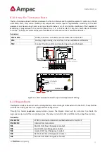
5.1
Connector numbering
Connector
Purpose /Pins
CN1
Link pins & when the front panel keyswitch is NOT used.
CN2
LCD Driver
CN3 & 4
LCD Back Lighting
CN5
Comms and +/- 27V and earth to the backpan boards. (Imax = 400mA)
Pins
& 0V
& +27V,
& RS 485 Bus,
Tx. Enable
CN6
Monitoring / Comms from the Power Supply.
Pins
& 0V
PSU Sense
PSU Adjust
Charger ON
Batt Load
Temp sense
Batt V Sense.
CN7
Factory Use Only
CN8
+/- 27V and earth from the Power Supply / Charger.
Pins
0V
+27V
Earth
CN9
Comms to the internal front panel cards. (Imax = 400mA)
Pins
Pin connections are the same as CN5
CN10
+27V and 0V to the Sounder, Agent Release and Fan Termination back plan boards (Imax
= P/S limit). All other backpan boards, 27VDC supply is via the RJ45 Comms cable.


