


MAN1565-4
27
–
Zone Indicators
There are two indicators for each of the eight zones.
Zone Alarm
–
Red (x8)
Each indicator will show if the individual zone it represents is in the alarm condition (flashing at
the alarm rate and then steady when the acknowledge control has been operated at the FACP).
Zone Indicators Fault /Isolated
–
Amber (x8)
Each indicator will show if the individual zone it represents is in a fault
condition (flashing at the fault rate, isolation of the zone will change the LED condition to steady). Note: The isolate
condition has priority.
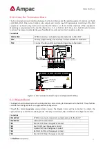
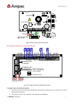
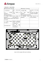
6.14
Agent Release Control
Agent Release control consists of an Agent Release Module, Termination Board and an optional Local Control Station.
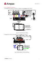
6.15
Operation
Introduction
The Agent Release Module and Termination Board communicate with the FACP via the RS485 multi-drop bus.
The Local Control Station communicates only with the Termination Board via a separate RS485 bus. Up to 4 Local
Control Stations can be connected to one termination board.
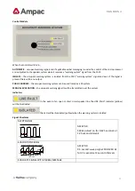
Agent discharge operates in two modes
–
automatic and manual. The manual mode is selected by pressing the Inhibit
switch on any Local Control Station. To indicate the system is in manual the Inhibit LED will be illuminated. Pressing
Inhibit again will toggle or return the mode to automatic and extinguish the Inhibit LED.
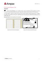
The “Agent Released” Pressure Switch (PSW) is wired to the PSW input on the Termination Board and is used t
o
confirm that the agent has been released. The circuitry involved in this process can be configured to accept a normally
open contact, normally closed contact, normally open mechanically operated (manual) or is ignored (not fitted) and is
selected via FACP on-site programming. If the mechanical (manually operated) option is selected the module monitors
the pressure switch input and provides notification the agent has been released manually, initiates an alarm and
illuminates the “Agent Released “ indicator
.
Manual Mode
When the system is in manual mode, then;
➢
The Local Control Station Inhibit indicator is lit at the FACP and all Local Control Station’s.
➢
The buzzer at all Local Control Stations will sound until the inhibit button is released.
➢
The System Inoperative output is turned on.
➢
The Automatic discharge sequences are prevented from starting.
➢
If an automatic discharge sequence was underway and the inhibit switch is activated (switched to manual
mode) the discharge sequence is aborted and the sequence is reset. This means the Stage 1 and Stage 2
outputs are switched off.
To manually discharge the agent the “ Lock Off Valve “ must be open and the Manual Release switch on the Local
Control Station pressed. The manual discharge sequence is;
➢
Manual Activation indicator is lit on the FACP and Local Control Station.
➢
The FACP activates its brigade alarm output.
➢
Stage 1 outputs are switched to +24VDC. (FIRE ALARM sign illuminated, aural alarm sounds)


