


MAN1565-4
12
6
Expanding the FACP with compatible Ancilliary Board
The addition of or a combination of the modules / boards / cards listed below and mounted on the back pan or the
front panel of the FACP provide additional control and monitoring facilities to a standard panel. All board inputs or
outputs are programmable to any combination of zones.
Note:
Only one of each board type can be installed in any one panel. The board types are:
➢
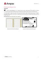
Switch and Indicator Card BRD25GIB
➢
Input Board BRD25SIPB.
➢
Relay Board, BRD25EWRB
–
A ( Panel Use )
➢
Remote Relay Board BRD25EWRB
–
B ( Remote Use )
➢
Sounder Board BRD25SOPB.
➢
Fire Fan Module consists of a Termination Board BRD25FTB and front panel card BRD25FCB -.
➢
Brigade Interface Board BRD25BBA.
➢
Agent Release Control consists of a Termination Board BRD25ATB and front panel card BRD25ARB.
➢
General Indicator Card. BRD25GIB -A
➢
LED Annunciator Master BRD25GIB
–
E
➢
Occupant Warning System EV20, EV40, EV60 and EV120
Note:
To add or remove Add-O
n’s from the FACP go to the SYSTEM and PROGRAM Menus.
Note:
Refer to man
ual MAN1564 “ZoneSense Plus 2008 AS programming” for
instructions on programming the
above Add-
On’s
6.1
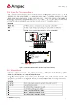
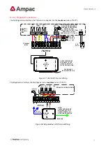
Internal Communications Connector (RS485)
PCB mounted connectors provide serial communications to internal ancillary boards. CN9 on the Main Card cables to
CN1 or 2 on the front panel cards and CN5 on the Main Card cables to CN1 or 2 on the back pan boards.
6.2
Programming
Refer to the Operation and Programming Manual for instructions on programming the above Add-
On’s into the
FACP.
Note:
The Configuration Label should be updated once the panel has been upgraded.


