background image

75

Section 6: Corrective Maintenance
Hale Products, Inc., May 2005, Rev.-B

  Corrective Maintenance   

6

Repair

6.1

OVERVIEW

This section describes the removal, inspection, and reinstallation (as 
required for maintenance and repair) of the Hale pump and gearbox compo-
nents.  Follow the disassembly instructions in the order in which they 
appear in this section.  At any point in the disassembly process, the unit can 
be reassembled by following the instructions in the reverse.

Service should be performed by a trained and qualified service technician, 
or your authorized Hale Products service representative.  Be sure you have 
sufficient knowledge, experience and the proper tools.

Wherever there is a requirement for new parts, it is recommended to use 
only Hale authorized replacement parts for optimum safety of the equip-
ment and its operators and to limit “downtime.”

6.2

GENERAL REPAIR GUIDELINES

Before You Begin...

For a parts breakdown and identification, see Section 9, heading “Drawing 
Package” on page 151.

READ ALL INSTRUCTIONS THOROUGHLY

BEFORE BEGINNING ANY SERVICE REPAIR.

1.

Place apparatus out of service in accordance with your departmental 
procedures.

2.

Park the vehicle on a level surface.  Set the parking brake and chock the 
front and rear wheels in accordance with your departmental procedures.

3.

Match mark, tag and/or note, or photograph the orientation of all 
mechanical and electrical components and connections to the pump 
and/or gearbox before disassembly.  This aids in proper reassembly.

4.

Determine best method for servicing, i.e., servicing while in the appara-
tus or removal from the top or bottom of the apparatus.

Summary of Contents for Silencer AP Series

Page 1: ...M Manual p n 029 0020 83 0 Hale Products Inc A Unit of IDEX Corporation 700 Spring Mill Avenue Conshohocken PA 19428 U S A Telephone 610 825 6300 FAX 610 825 6440 Web www haleproducts com Installatio...

Page 2: ...o follow the instructions on care and operation Proper use and good preventive maintenance will lengthen the life of your unit ALWAYS INCLUDE THE UNIT SERIAL NUMBER IN YOUR CORRESPONDENCE ECO NO REV C...

Page 3: ...Two Stage Centrifugal High Volume High Pressure Attack Pump 500 750 GPM 1 893 2 893 LPM 21 5 47 3 LPS three primary drive options truck transmission PTO hydraulic drive H or direct engine mount M The...

Page 4: ...Overview 4 Silencer Series Booster Pump p n 029 0020 83 0 well as the drive unit Table A 1 Booster Pump Model Number Matrix...

Page 5: ...5 Silencer Series Booster Pump p n 029 0020 83 0 Overview Figure B Overview Silencer Booster Pump For shim installa tion see Step Fig ure B Overview Silencer Booster...

Page 6: ...Overview 6 Silencer Series Booster Pump p n 029 0020 83 0...

Page 7: ...TING TO INSTALL OR OPERATE THE PUMP WHEN DEVELOPING DEPARTMENTAL APPARATUS OPERATING PROCE DURES INCORPORATE THE WARNINGS AND CAUTIONS AS WRITTEN Hale is a registered trademark of Hale Products Incorp...

Page 8: ...MMEND REPLACING FASTENERS WITH ANYTHING OTHER THAN HALE PART NUMBERS PROVIDED REPLACING WITH A WEAKER ALTERNATIVE POSES A SERIOUS SAFETY RISK ALL FASTENERS MUST BE INSTALLED WITH A LOCKING ANAEROBIC A...

Page 9: ...nd gearbox assemblies for proper fluids to use and quantities required DO NOT permanently remove or alter any protective feature guard or insulating devices or attempt to operate the system when these...

Page 10: ...on on page 19 for additional information Relieve all system pressure then drain all water from the system before servicing any of its component parts Use only pipe hose and fittings which are rated at...

Page 11: ...the pump Also see Section 3 Basic Operation on page 33 for additional information DO NOT reduce the pressure on the INTAKE gauge below zero 0 Serious damage to the water main could result Some vehicle...

Page 12: ..._____________________________________________________________________ ______________________________________________________________________ ___________________________________________________________...

Page 13: ...ntrifugal pump SPEED RPM If the speed of rotation increases with flow held constant fluid pressure increases PRESSURE If pressure changes with speed held constant the flow measured in gallons or liter...

Page 14: ...er vanes develop dis charge pressure and via the cutwater directs the water to the discharge opening The cutwater is a wedge that divides the water between the volute pump body and the pump discharge...

Page 15: ...olute throat Note Stainless Max pumps volute and impeller are constructed of corrosion resistant stainless steel Models SMM SMD and SMR Series This gradual increase in size maintains a con stant avera...

Page 16: ...learance between the spinning impeller and the stationary clearance ring Also see Figure 2 3 Typical Pump and Gearbox Overview on page 15 Typically a clearance ring has a radial clearance of about 0 0...

Page 17: ...the impeller and input shafts for smooth opera tion Anti friction bearings are used and offer a major contribution to the life of a pump When replacing bearings it is important that you do not interch...

Page 18: ...take being added to the prssure developed by both impellers and and the amount of water delivered to the discharge This is the sum of the flows of the two impellers For example if the inlet pressure i...

Page 19: ...ing the transfer valve from volume to pressure operation the pressure will be doubled You may hear a metallic click or two clicks which will be the check valves closing If the clicks sound too harshly...

Page 20: ...o dis charge more than 50 percent of its rated capacity Be certain to warn everyone involved before switching between volume and pressure operation 3 Reduce the pump pressure to 50 60 PSI 3 4 BAR befo...

Page 21: ...a variety of ratios to accommodate most manufacturer requirements for engines trans missions and PTOs speed and available horsepower Gearboxes are also available with various mounting configurations e...

Page 22: ...Introduction 22 Section 2 Introduction Hale Products Inc May 2006 Rev B...

Page 23: ...rent conducting materials are connected electrically and exposed to fluid This results in corrosion of the less resistant of the two metals while the more resistant metal is protected See Figure 2a 1...

Page 24: ...cooler circulates pump water to transfer heat from the gearbox oil to the pump discharge thus maintaining proper operating temperatures Heat Exchanger K Series The Hale Model K heat exchangers meet NF...

Page 25: ...cessories Options Note For additional information about the pressure and relief valves in your sys tem see the separate manual provided with the valves Also see Section 9 Drawing Package on page 23 Fi...

Page 26: ...or light on the operator control panel signals when the valve is open See Figure 2a 4 P Series Relief Valve Control The P series relief valve system includes a panel mounted control valve PM and a rel...

Page 27: ...he valve automatically OPENS When the temperature returns to a safe level the valve CLOSES TRV L Kit The TRV L kit includes a chrome panel placard with a warning light a light test button and a pre as...

Page 28: ...e self lubricating for maintenance free operation An ESP priming pump also uses a single control to open the priming valve and start the priming motor See separate manual Hale p n 029 0810 01 0 for ad...

Page 29: ...PVG Priming Valves Pulling the handle out OPENS the valve and energizes the primer motor Pushing the handle in de energizes the motor and CLOSES the valve Figure 2a 8 PVG Priming Valves 2A 5 PUMP SHIF...

Page 30: ...iew It uses available apparatus vacuum or air pressure for power and is acti vated by an in cab pump shift control valve See Figure 2a 10 Pump Shift Control Valve The system includes a three position...

Page 31: ...f Hale pumps SVS valves enable the operator to shut off flow completely or throt tle the flow rate from a trickle to full flow See Figure 2a 11 Typical SVS Valve Primary Components Figure 2a 11 Typica...

Page 32: ...Accessories Options 32 Section 2a Accessories Hale Products Inc May 2006 Rev B...

Page 33: ...PERATING PROCEDURES SETTING WHEEL CHOCKS AS WELL AS LAYOUT AND CONNECTION OF HOSES VALVES AND DRAIN COCKS ALL VALVES DRAIN COCKS AND CAPS SHOULD BE CLOSED NEVER ATTEMPT TO SHIFT THE PUMP TRANSMISSION...

Page 34: ...transmission to the NEUTRAL position See WARNING note on page 33 3 Make sure the truck is at a complete stop before you attempt to shift from ROAD to PUMP Also see heading Pump To Road Shift Procedure...

Page 35: ...r For most pumpers this is direct drive 1 1 ratio In addition the speedom eter should register after the shift has been completed If the shift does not complete shift the transmission back to NEUTRAL...

Page 36: ...37 CAUTION DO NOT REDUCE THE PRESSURE ON THE INTAKE GAUGE BELOW DEPART MENT LIMITS SERIOUS DAMAGE TO THE WATER MAIN COULD RESULT 11 If the master intake gauge shows a vacuum before the desired dischar...

Page 37: ...positive inlet pressure it may be necessary to adjust the TPM relief valve to a point where water is dumping to the ground The internal relief valve is always opened first and if it cannot handle the...

Page 38: ...ing lights illuminate indicating a complete shift See Fig ure 3 1 Driver s Compartment Indicator Lights on page 35 Note If the truck manufacturer uses another in cab valve to achieve pump shift or off...

Page 39: ...GE WATER TO THE GROUND WITHIN 30 TO 45 SECONDS DO NOT CONTINUE TO RUN THE PRIMING PUMP STOP THE PUMP AND CHECK FOR AIR LEAKS OR POSSIBLE PROBLEMS SEE SECTION 5 TROUBLESHOOTING ON PAGE 67 7 Monitor the...

Page 40: ...DLE and close the discharge valves To resume pumping open the throttle and discharge valves If the pump overheats from continued churning without water flow open the discharge valves periodically to r...

Page 41: ...OR ATTEMPT TO PUMP UNTIL ALL THE GREEN PUMP LIGHTS IN THE CAB AND PANEL ARE ON DO NOT OPEN THROTTLE UNLESS ALL GREEN PUMP INDICATOR LIGHTS ARE ON SEE FIGURE 3 2 PUMP OPERATOR S PANEL ON PAGE 36 6 Ope...

Page 42: ...tructions Also see heading Post Operation Procedures on page 50 3 4 PUMPING IN RELAY Relay pumping is the movement of water through a number of consecutive pumpers from suction to discharge Relay oper...

Page 43: ...for 5 127 mm large diameter hose or 135 PSI 9 BAR 0 9 MPa for 6 152 mm hose per NFPA Standards 1962 See heading Pumping From a Hydrant General Operation on page 34 Also see heading Pumping From Draft...

Page 44: ...EM PUMPING OPERATION IT IS POS SIBLE TO SUPPLY GREATER PRESSURE THAN THE HOSE CAN WITHSTAND PRESSURE SUPPLIED TO THE HOSE SHOULD NOT EXCEED THE PRESSURE AT WHICH THE HOSE IS ANNUALLY TESTED BY THE DEP...

Page 45: ...G PROCEDURES 3 6 PUMP TO ROAD SHIFT PROCEDURES For Split Shaft Gearboxes 1 Verify that the operator s hand throttle or governor control is at IDLE speed 2 Shift the truck transmission into the NEUTRAL...

Page 46: ...correct procedure based on how the truck is equipped See Figure 3 3 TPM PMD Relief Valve Control on page 47 Some trucks may utilize a governor in place of the relief valve Standard Relief Valve Proced...

Page 47: ...above the normal operating pressure More complete and detailed information is found in the relief valve manual CAUTION THE PRESSURE INDICATOR ON THE PANEL IS ONLY A ROUGH INDICATION OF TPM SETTING AL...

Page 48: ...ure 3 3 TPM PMD Relief Valve Control on page 47 Turn the handwheel slowly clockwise until the AMBER light just goes out Then turn the handwheel one additional full turn clockwise CAUTION THE TPM PRESS...

Page 49: ...the engine WARNING DO NOT ATTEMPT EMERGENCY SHIFT PROCEDURES WHILE THE ENGINE IS RUNNING 6 Employ manual override procedure at the shift cylinder on the pump gear box as follows An eyebolt is provided...

Page 50: ...mp drain lines should be connected to this valve On two stage pumps move the transfer valve back and fourth between the VOLUME and PRESSURE positions 4 If sea water dirty water alkaline water or foam...

Page 51: ...ocal maintenance and test procedures 4 2 POST OPERATION 1 Inspect the suction hose rubber washers and washers in the suction tube caps Remove foreign matter from under these washers Replace worn damag...

Page 52: ...ro cedures Always follow local maintenance and test procedures Test the relief valve system see page 52 Test the priming system see page 53 Establish and HOLD prime control for about three 3 to five 5...

Page 53: ...d wheel turns freely Observe the pressure gauge and indicator light for proper valve operation 5 Return the relief valve hand wheel and the apparatus to normal operational condition Priming System 1 T...

Page 54: ...arge hose drain and multi drain valves and valve linkage with a good grade lithium base grease Note The PMD valve should be lubricated every six 6 months Transfer Valve Test Two Stage Pumps Only 5 For...

Page 55: ...doubled Intake Strainers Check and clean any debris from the intake Flush the pump if required using departmental company procedures Repair or replace any damaged strainers Auxiliary Engine See engine...

Page 56: ...thly maintenance includes the weekly maintenance procedures plus Valve lubrication see page 56 Gearbox lubrication see page 56 Checking the pump and drive line bolts see page 57 Relief valve system ch...

Page 57: ...shop rags and oil dry handy and a suitable container to collect the fluid 3 The oil level should be up to the bottom of the oil drain port hole 4 If the oil appears white or milky a water leak is ind...

Page 58: ...least one air leak Vacuum leaks can often be detected by ear if the apparatus engine is turned OFF Correct leaks immediately before returning the pump to ser vice 6 Test the suction hose as follows A...

Page 59: ...if installed see page 61 Also see separate manual provided Yearly pump test to check performance levels including Tank to Pump Flow Rate see page 62 Also see NFPA 1911 standard for more details Repla...

Page 60: ...f Valve System Check 1 Place apparatus out of service in accordance with departmental proce dures 2 Test relief valve system in accordance with weekly maintenance check Also see heading Weekly on page...

Page 61: ...he pump and test for proper operation See separate manual provided Hale p n 101 2850 02 0 IIMPORTANT DO NO USE A LUBRICANT ON THE PUMP VANES AND VANE SLOTS LUBRI CANT AND COLD WATER FORM AN EVENTUAL G...

Page 62: ...d during this time to prevent pump overheating 7 Reopen the discharge valve and check the flow through the nozzle using a Pitot tube or flow meter Adjust the engine throttle to bring the pressure to t...

Page 63: ...scharge valves as required to maintain pressure Notes For 750 GPM 2 839 LPM 47 LPS test two 2 1 2 64 mm lines should be laid from the pumper to the nozzle For 1 000 GPM 3 785 LPM 63 LPS test three lin...

Page 64: ...Series Pumps rated at 750 GPM and 1 000 GPM 2 839 and 3 785 LPM 47 and 63 LPS a three 3 hour test is required Two 2 hours at FULL capacity and at 150 PSI 10 BAR 0 4 MPa Thirty 30 minutes at 70 capacit...

Page 65: ...service proceed to Section 6 heading Impeller Single Stage Pumps on page 100 Often replacement of the clearance rings reduces the bypass and restores the pump to near original performance A complete r...

Page 66: ...Preventive Maintenance 66 Silencer Series Booster Pump p n 029 0020 83 0...

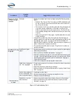
Page 67: ...nel and or the side of the gearbox Figure 5 1 Sample Serial Nameplate Condition Possible Cause Suggested Corrective Action PTO Will Not Engage Consult the PTO manufacturer s instructions WARNING DO NO...

Page 68: ...er Remove obstruction from suction hose strainer Thoroughly clean strainer screen Suction connections Clean and tighten all suction connections Check suction hose and hose gaskets for possible defects...

Page 69: ...lve outlet con nection and retest Insufficient Pump Capacity Chart continued on next page Insufficient engine power Engine power check and tune up may be required for peak engine and pump performance...

Page 70: ...Difficult to Oper ate Lack of lubrication Lubricate the remote control linkages and collar with oil For lubri cant recommendations see Appendix C1 Lube and Sealant Specifications on page 133 Engine S...

Page 71: ...Air leak Verify that the air bleeder on the suction tube is NOT open Locate and eliminate all air leaks during maintenance Drafting too high Verify lift hose hose friction water temperature and other...

Page 72: ...low maintenance instructions for disassembly cleaning and lubrication Unable to Obtain Proper Setting on Relief Valves Using the wrong proce dures Check instructions for setting the relief valve and r...

Page 73: ...and possibly more frequent oil changes are needed Leaking oil seal or mechanical seal Inspect the oil seals and replace as needed If the oil seal checks OK the mechanical seal may be leaking There mus...

Page 74: ..._________________________________________ ______________________________________________________________ ______________________________________________________________ ________________________________...

Page 75: ...rts it is recommended to use only Hale authorized replacement parts for optimum safety of the equip ment and its operators and to limit downtime 6 2 GENERAL REPAIR GUIDELINES Before You Begin For a pa...

Page 76: ...ACING FASTENERS WITH ANYTHING OTHER THAN HALE PART NUMBERS PROVIDED REPLACING WITH A WEAKER ALTER NATIVE POSES A SERIOUS SAFETY RISK ALL FASTENERS MUST BE INSTALLED WITH A LOCKING ANAEROBIC ADHESIVE S...

Page 77: ...ING DO NOT TOUCH THE CARBON SEAL WHILE INSTALLING THE MECHANICAL SEAL USE OF ANY OTHER LUBRICANT CAN DAMAGE THE MECHANICAL SEAL AND SEAT 11 Use a pusher or bearing installation tool when installing be...

Page 78: ...l components bearings seals gears etc for excessive or abnormal wear i e pitting scoring scratches cracks splits etc IMPORTANT WHEN REASSEMBLING ALL COMPONENTS MUST BE CLEAN AND FREE OF DEFECTS 2 Repl...

Page 79: ...ARING MANUFACTURER S COMPONENTS THE BEARING RACE AND CONE MUST ALWAYS BE REPLACED IN MATCHING SETS AS SUPPLIED BY THE MANUFACTURER Tools Required Lifting gear lever hoist or chain hoist and short chok...

Page 80: ...orrective Maintenance Hale Products Inc May 2006 Rev B N 06 or N 07 bearing nut socket or spanner wrench available from Whittet Higgins at www whittet higgins com or 35 Higginson Avenue P O Box 8 Cent...

Page 81: ...ncer Series Booster Pump p n 029 0020 83 0 Corrective Maintenance 6 4 SILENCER BOOSTER PUMP OVERVIEW Figure 6 2 Silencer Series Booster Pump For shim installa tion see Step 11 Shaft End Play Float on...

Page 82: ...ve Maintenance heading Replace Gearbox Oil on page 58 Have a suitable container available to collect excess fluid approximately two 2 quarts 2 liters 5 Disconnect the drive shaft from the gearbox Note...

Page 83: ...of Loctite to the fas teners and torque to PTO manufacturer s specifications 6 Connect all components to the gearbox then fill the gearbox with oil to the proper oil level See Section 4 Preventive Mai...

Page 84: ...aft 3 Remove the shaft key and the flange retaining ring 4 Carefully remove pry out the oil seal making sure not to damage the bore shaft or roller bearing Removing the seal renders it defective Repla...

Page 85: ...cal Bearing and Seal Insertion Tool Drawings If the seal bearing tool is not available cover the flange retaining ring groove with thin electrical tape to avoid cutting the oil seal as it is inserted...

Page 86: ...al Volute All Except TBP on page 93 and Impeller All Except TBP on page 95 Volute and Impeller TBP Only on page 99 Mechanical seal on page 103 2 Remove the four 4 7 16 14 screws securing the pump head...

Page 87: ...nstall the oil seal with the spring side of the seal facing into the gearbox Replace all gaskets where applicable Apply a coating of general purpose grease to the gasket and align to the pump head Ins...

Page 88: ...seal pump head and pump shaft oil seal These must be removed to enable the gearbox to be separated from the pump For removal instructions seesee heading Servicing the Booster Pump All Except TBP on pa...

Page 89: ...aft key and the flange retaining ring 5 Remove pry out the oil seal making sure not to damage the bore shaft or bearing Removing the oil seal renders it defective Replace with Hale P N 296 2650 00 0 6...

Page 90: ...il flush against the snap ring Lightly tap the seal around the edges to ensure an even flush seat Make sure to install the oil seal with the spring side of the seal facing into the gearbox See Figure...

Page 91: ...ceding sections Before You Begin on page 81 and Cleaning and Inspection Guidelines on page 84 2 Using a press install the pump side bearing cone onto the pump shaft making sure it is properly aligned...

Page 92: ...ring cover and gasket and tighten the four 7 16 14 screws in a cross pattern to insure a proper seal Tighten until the shaft barely spins Using feeler gauges or dial indicator gauge measure the gap be...

Page 93: ...page 94 The volute is secured by hex screws quantity dependent on pump model Replace the volute gasket whenever the volute is removed 1 Remove the suction manifold if still installed 2 Unthread the c...

Page 94: ...Corrective Maintenance 94 Silencer Series Booster Pump p n 029 0020 83 0 Figure 6 8 Booster Pump Parts Breakdown...

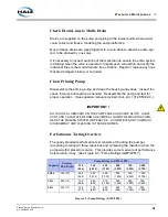
Page 95: ...ee Figure 6 8 Booster Pump Parts Breakdown on page 94 1 Remove the volute pump body to expose the impeller clearance rings and mechanical seal 2 Remove the cotter pin from the impeller nut and set saf...

Page 96: ...iew preceeding sections Before You Begin on page 73 and Clean ing and Inspection Guidelines on page 76 Install the impeller shaft key into the slot on the pump shaft CAUTION DO NOT STRIKE THE IMPELLER...

Page 97: ...placed See Figure 6 9 Clearance Ring ID and Impeller ID OD Measure ment Note Clearance rings should be measure while pressed into the body When new the radial clearance between the impeller hubs and t...

Page 98: ...utside wear limit a new impeller must be installed If the clearance rings on the booster pump show significant wear but the impel ler itself is within the size tolerance undersized clearance rings can...

Page 99: ...ater Cooling Lines Left Side and See Figure 6 11 Typical Water Cooling Lines Right Side 3 Remove the 7 16 14 screws and hardware securing the discharge manifold to the volute and remove the manif old...

Page 100: ...LLER OUTBOARD 1ST STAGE CHECK VALVE PRESSURE SERIES OPERATION CHECK VALVE VOLUME PARALLEL OPERATION SCREWS 7 16 14 8 CHECK VALVE HOUSING SCREWS 7 16 14 8 DISCHARGE MANIFOLD SCREWS 7 16 14 DISCHARGE MA...

Page 101: ...CERTAIN THE WEDGES OR PULLER IS PLACED AT THE IMPELLER VANES TO AVOID IRREPARABLE DAMAGE Notes Tap the pump shaft end using a dead blow hammer to free the impeller from the pump shaft Use care to avo...

Page 102: ...ection For opposite engine pumps the cast arrow on the volute will be on the right side and will be pointing in a counter clockwise direction 5 Put the outboard impeller back on the pump shaft Use car...

Page 103: ...ad ing Impeller All Except TBP on page 95 1 From within the pump head and using two jaw type puller tools hook type spaced 180 apart reach in and pry pull the seal ring from the pump shaft Note On pum...

Page 104: ...LEANED WITH AN APPROPRIATE DEGREASER AND A SOFT CLOTH E G ALCOHOL WIPES SUPPLIED WITH THE HALE SEAL INSTALLATION KIT OIL AND GREASE INCLUDING SKIN OILS WILL DAMAGE THE MECHANICAL SEAL FACE NEVER TOUCH...

Page 105: ...assembly in until the two running faces contact 6 The seal insertion tool is available from Hale order P N 029 0760 00 0 If necessary the seal insertion tool can be made of plastic or brass to the di...

Page 106: ...l TBP Mechanical Seal Assembly on page 106 and spring 6 Place two hook type tools or two small screw drivers 180 apart between the diaphragm assembly and the stationary sealing face Using steady gentl...

Page 107: ...SE RUBBER LUBRICANT EMULSION OR EQUIVALENT ON THE RUBBER MECHANICAL SEAL PARTS TO EASE INSTALLATION USING ANY OTHER LUBRICANT CAN DAMAGE THE SEAL AND SEAT 1 Clean the bore of the pump head and pump sh...

Page 108: ...e to locate the spring on the diaphragm assembly s pilot 9 Slide the spring retainer onto the pump shaft and secure in place with the retaining ring See Figure 6a 3 Typical TBP Mechanical Seal Assembl...

Page 109: ...m the transfer valve cover Pull up on the transfer drum cover to remove the transfer drum and components as an assembly 6 Remove the square seal ring 7 Remove the 2 1 2 non locking cover 8 Remove the...

Page 110: ...029 0020 83 0 Cam Handle Cover Retainer Non locking Cover Retaining Ring Transfer Valve Cover Locating Pin O ring 2x Bronze Bushings Square Seal Ring Transfer Drum Transfer Drum Sleeve Bore Bolt and W...

Page 111: ...alve cover and install square seal ring in the groove and the bore of the transfer valve sleeve 10 Apply grease to top of discharge manifold and install the transfer drum assembly into the transfer dr...

Page 112: ...ulic motor from the hydraulic adapter flange Unbolt motor and pull back to slide motor shaft splined from the input shaft coupling 3 Remove the four 4 7 16 14 hex screws and hardware securing the hydr...

Page 113: ...rse order Using Loctite 242 removable medium strength thread lock install the 1 2 13 and 7 16 14 mounting screws and hardware For sealant specifications also see Appendix C1 Lube and Sealant Specifica...

Page 114: ...ocess you may want to make a sketch of the plumbing and component configuration to aid in re assembly 2 If not already done remove the necessary enclosures to gain access to the Silencer Series booste...

Page 115: ...sing See Figure 6c 3 Engine Drive Option M Always use proper lifting and support apparatus jacks hoists straps chain etc when servicing the unit Exercise care when using chains to protect fin ished su...

Page 116: ...lements in the coupling according to the Cleaning and Inspection Guidelines on page 76 Installation Notes Engine Mounting 1 Review sections Before You Begin on page 73 and Cleaning and Inspec tion Gui...

Page 117: ...two sided tape to hold the disks in place as you slide the assembly onto the input shaft IMPORTANT IF YOU ARE USING A 3 BELL HOUSING THE RETAINING RING IS NOT USED HOWEVER IF YOU ARE INSTALLING A 4 B...

Page 118: ...TED ON THE INSTALLATION DRAWING SEE SEPARATE SECTION DRAWING PACKAGE ON PAGE 133 LOCATED AT THE BACK OF THIS MANUAL WARNING THE HALE PUMP AND GEARBOX ASSEMBLY ARE HEAVY AND BULKY ADDING ACCESSORIES IN...

Page 119: ...iew and Figure 7 2 TBP Pump Front View Refer to installation plate PL1180AA for weight and center of gravity 7 3 DRIVELINE ISSUES Drive Line and Flange Bolts Ensure that All bolts are tight Use a torq...

Page 120: ...nalysis software such as Dana s The Expert during driveline layout Dana s software is available free on the World Wide Web at http www2 dana com expert When performing calculations strive to achieve t...

Page 121: ...rmation provided under this heading Driveline Issues Driveline design and truck system integration is the responsi bility of the apparatus manufacturer Failure to comply with the driveline parame ters...

Page 122: ...and gear box assemblies are drained prior to shipping from the factory IMPORTANT AT INSTALLATION AND BEFORE OPERATING FOR THE FIRST TIME OIL MUST BE ADDED TO THE GEARBOX TO THE APPROPRIATE LEVELS FOR...

Page 123: ...and well lubricated Linkage joints should be lubri cated regularly Plumbing interferences When running remote linkage lines be care ful that they DO NOT come in contact with the pump plumbing or other...

Page 124: ...Installation 124 Basic Installation Hale Products Inc August 06 Rev B...

Page 125: ...e away from the center of rotation Force Centrifugal A pump that uses a rapidly spinning disk or impeller to create the pressure for fluid Pump movement Certification Pumper test in accordance with NF...

Page 126: ...sure changes by controlling engine speed to maintain pump discharge pressure Horsepower A measure of mechanical work Impeller The working part of a centrifugal pump that when rotating imparts energy t...

Page 127: ...ft A midship pump is usually mounted with a split gearbox installed in the drive shaft The pump shift moves a sliding gear in the gearbox that transmits power either to the pump or the rear axle In RO...

Page 128: ...o produce rotation Transfer Valve A two position valve in a pump that changes the operation from parallel volume to series pressure operation and vice versa not used on single stage pumps Vanes Guides...

Page 129: ...Feet of Water One Inch of Mercury 1 132 Feet of Water One Pound per Square Inch 2 0178 Inches of Mercury equals 27 68 inches of Water One Cubic Meter 1 000 Liters One Imperial Gallon 1 2 Gallons CONVE...

Page 130: ...Appendix A Glossary Measurements Hale Products Inc July 2006 Rev B Hale Products Inc A Unit of IDEX Corporation 700 Spring Mill Avenue Conshohocken PA 19428 U S A Telephone 1 610 825 6300 Fax 1 610 82...

Page 131: ...smis sion Lube SAE 50 Trans Mack Truck Company 2100 Mack Boulevard Allentown PA 18105 D A SynSure Synthetic Lube SAE 50 Trans D A Lubricant Company Incorporated 1340 West 29th Street Indianapolis IN 4...

Page 132: ...ers Point Avenue Long Island City NY 11101 Valvoline HD Synthetic Trans Oil SAE 50 Trans Valvoline Incorporated A Subsidiary of Ashland Oil Inc 3499 Blazer Parkway Lexington KY 40512 Alternate LOW Tem...

Page 133: ...E 50W 80W 90 75W 80 Synthetic Lubricants must meet service rating API GL 5 SMR A SMR U SMR AC Pedestal Long Short 0 75 1 5 pints 0 71 10W 40 to 15W 40 Multi Grade Engine Oil Lubricants must meet servi...

Page 134: ...6 High Temperature Removable Threadlock or equivalent primarily for gearbox assembly 242 Medium Strength Threadlock or equivalent primarily for pump assembly Oil See Appendix C Alternate Lubricant Man...

Page 135: ...473 24 1 7 13 0 9 750 2 839 20 1 4 11 0 8 5 0 4 30 114 99 6 8 14 0 96 150 568 35 2 4 18 1 2 1 000 3 785 34 2 4 20 1 4 8 0 6 40 151 176 12 0 24 1 7 4 0 3 175 662 47 3 2 25 1 7 6 0 4 1 250 4 732 53 3 7...

Page 136: ...ix D Hose Friction Loss Hale Products Inc July 2006 Rev B 136 Hale Products Inc A Unit of IDEX Corporation 700 Spring Mill Avenue Conshohocken PA 19428 U S A Telephone 1 610 825 6300 Fax 1 610 825 644...

Page 137: ...7 456 1 726 68 4 7 61 231 96 363 138 522 188 711 245 927 310 1 174 383 1 450 463 1 753 70 4 8 62 235 97 367 140 530 190 719 248 939 315 1 192 388 1 469 470 1 779 72 5 0 63 238 99 375 142 538 193 731 2...

Page 138: ...3 309 994 3 763 1 258 4 762 1 553 5 879 2 236 8 464 72 5 0 567 1 146 666 2 521 772 2 922 886 3 354 1 008 3 816 1 276 4 830 1 575 5 962 2 268 8 585 74 5 1 575 1 177 675 2 555 783 2 964 898 3 390 1 022...

Page 139: ...receiving Bubbles are created under the vacuum formed near the eye of the impeller Cavitation is often referred to as the pump running away from the fluid supply This means you are trying to pump mor...

Page 140: ...nd entirely on the vacuum compound gauge to indicate when a pump is nearing cavitation The vacuum gauge is usually installed several inches away from the leading edge of the impeller eye where the gre...

Page 141: ...suction strainer for blockage or effectiveness See heading Strain ers on page 142 Preventive Measures Consider the size of the suction hose Figure F 7 Hose Size vs Pump Rat ing Capacity on page 142 li...

Page 142: ...gged strainers or suction strainer selection restricting flow Verify the hose strainers and suction strainer are clear unobstructed and located deep enough in the water source to insure constant unint...

Page 143: ...143 Appendix F Cavitation Hale Products Inc Nov 2005 Rev A Cavitation...

Page 144: ...Cavitation 144 Appendix F Cavitation Hale Products Inc Nov 2005 Rev A...

Page 145: ...POSE OR USE QUALITY COURSE OF DEALING USAGE OF TRADE OR PATENT INFRINGEMENT FOR A PRODUCT MANUFACTURED TO ORIGINAL BUYER S DESIGN AND SPECIFICATIONS EXCLUSIVE REMEDIES If Buyer promptly notifies HALE...

Page 146: ...Hale Products Inc A Unit of IDEX Corporation 700 Spring Mill Avenue Conshohocken PA 19428 U S A Telephone 1 610 825 6300 Fax 1 610 825 6440 Web www haleproducts com...

Reviews: