


❑
Operation
36
Section 3: Operating
Hale Products, Inc., May 2005, Rev-B
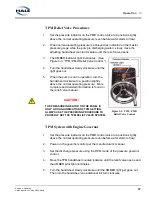
Figure 3-2: Pump Operator’s Panel
9.
Note the discharge and intake pressures, then gradually open the engine
throttle until the master discharge gauge indicates the desired pressure.
10.
Set the automatic relief valve according to your fire department policy, if so
equipped. If your fire department does not have a policy, see heading “TPM
Operation from a Hydrant” on page 37.
CAUTION !
DO NOT REDUCE THE PRESSURE ON THE INTAKE GAUGE BELOW DEPART-
MENT LIMITS. SERIOUS DAMAGE TO THE WATER MAIN COULD RESULT.
11.
If the master intake gauge shows a vacuum before the desired discharge
pressure or flow is achieved, you are receiving all the water that the suction
piping (hydrant) can supply.
12.
If you need to increase pressure when this occurs, pump flow must be
reduced or the water supply improved.
To increase pressure, reduce the pump flow. However, the master intake
gauge reading must be maintained at 5 PSI (0.34 BAR / 0.04 MPa),
minimum.
13.
As the throttle (engine speed) is increased, the pressure gauge reading
increases.
Summary of Contents for Silencer AP Series
Page 6: ...Overview 6 Silencer Series Booster Pump p n 029 0020 83 0...
Page 22: ...Introduction 22 Section 2 Introduction Hale Products Inc May 2006 Rev B...
Page 32: ...Accessories Options 32 Section 2a Accessories Hale Products Inc May 2006 Rev B...
Page 66: ...Preventive Maintenance 66 Silencer Series Booster Pump p n 029 0020 83 0...
Page 124: ...Installation 124 Basic Installation Hale Products Inc August 06 Rev B...
Page 143: ...143 Appendix F Cavitation Hale Products Inc Nov 2005 Rev A Cavitation...
Page 144: ...Cavitation 144 Appendix F Cavitation Hale Products Inc Nov 2005 Rev A...