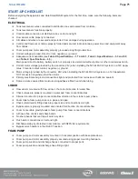


81
Page
81
SmartFOAM
OPERATION
DESCRIPTION
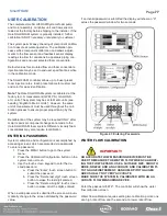
Operation of Hale SmartFOAM systems is controlled by the UltraView SmartFOAM controller display. The Hale SmartFOAM
system constantly monitors water and foam concentrate flow values, maintaining foam injection at the specified concentrate
injection rate. The system responds to variations in water flow by increasing or decreasing the speed of the foam pump.
On initial power up of the apparatus, the Hale SmartFOAM system begins a brief self-diagnostic routine (
). When
completed, the system enters the preset screen and waits for operator action or SAM remote (CAN) commands. SAM acti-
vates the foam system even if it is turned off (as long as power is applied).
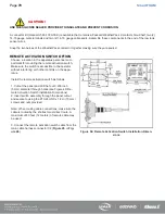
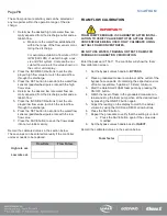
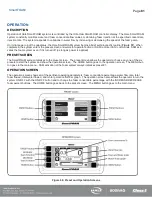
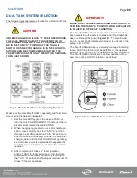
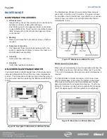
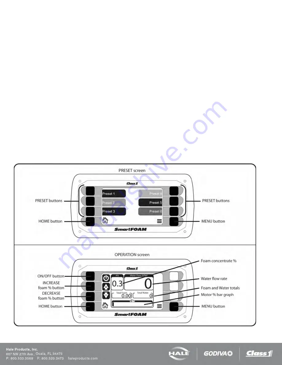
PRESET SCREEN
The SmartFOAM system initializes to the preset screen. The preset screen allows the operator to choose any one of the six
presets to start the system and show the operation screen. The HOME button goes to the operation screen. The MENU but-
ton goes to the main menu. SAM activation of the foam system always initializes preset #1.
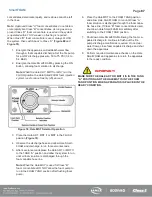
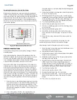
OPERATION SCREEN
The operation screen shows all of the pertinent operating parameters: foam concentrate percentage, water flow rate, total
foam flowed, total water flowed, and motor percent effort bar graph. The operation screen also allows the operator to turn the
system ON/OFF with the ON/OFF button and to change the foam concentrate percentage with the INCREASE/DECREASE
foam percent buttons. The HOME button goes back to the preset screen. The MENU button goes to the main menu.
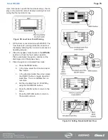
Figure 66: Preset and Operation Screens
Summary of Contents for MiniCAFS 2.1A
Page 3: ...Page 2 SmartFOAM NOTES...
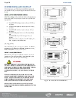
Page 16: ...Page 15 SmartFOAM SYSTEM DIAGRAM Figure 6 Typical Hale SmartFOAM 2 1A and 1 7AHP System...
Page 17: ...Page 16 SmartFOAM Figure 7 SmartFOAM 3 3 5 0 6 5 Single Tank System with In line Strainer...
Page 18: ...Page 17 SmartFOAM Figure 8 SmartFOAM 3 3 5 0 6 5 Single Tank withMSTandIn lineStrainer...
Page 19: ...Page 18 SmartFOAM Figure 9 SmartFOAM 3 3 5 0 6 5 Single Tank withMSTandFSSeriesStrainer...
Page 20: ...Page 19 SmartFOAM Figure 10 SmartFOAM 3 3 5 0 6 5 Dual Tank withMDTIIandIn lineStrainers...
Page 21: ...Page 20 SmartFOAM Figure 11 SmartFOAM 3 3 5 0 6 5 Dual Tank withMDTIIandFSSeriesStrainer...
Page 22: ...Page 21 SmartFOAM Figure 12 SmartFOAM 3 3 5 0 6 5 Dual Tank withADTandIn lineStrainers...
Page 23: ...Page 22 SmartFOAM Figure 13 SmartFOAM 3 3 5 0 6 5 Dual Tank withADTandFSSeries Strainers...
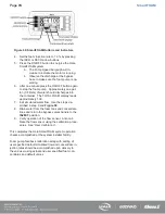
Page 48: ...Page 47 SmartFOAM Figure 28 Typical 4 Inch Check Valve Installation Midship Pump...
Page 59: ...Page 58 SmartFOAM Figure 43 ADT Option Air Hose Connections Part 2...
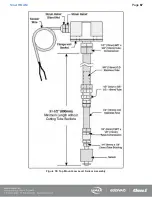
Page 68: ...Page 67 SmartFOAM Figure 55 Top Mount Low Level Sensor Assembly...
Page 77: ...Page 76 SmartFOAM NOTES...
Page 90: ...89 Page 89 SmartFOAM NOTES...


