6 / 14
Hakki Feed 472
Translation
Version 1
3.1.1.
Connecting the hydraulics
Use the operator’s manual of the
relevant Hakki Pilke firewood processor
for the connections!
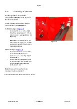
Use of the table requires two separate
control valves: Example
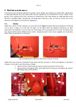
Figure 3.
In-feed conveyor A
-
Connected in series to the Hakki
Pilke firewood processor’s in-feed
system (quick couplings
C
(red) and
D
(black))
Note!
If the machine features the
valve shown in Figure 3, it must be
opened to ensure oil flow through
the quick couplings.
Chain conveyor B
-
Connected to the accessory valve
of the Hakki Pilke firewood
processor (quick couplings
A
(red)
and
B
(black))
-
Chain conveyor motor’s spill hose
(from the motor end): connect the
hose directly to the machine’s
hydraulic oil tank
Note!
Dispenser D runs when chain
conveyor B is being operated.
Figure 3.
Ensure that all connections are safe and secure!


