background image


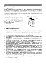
The  installation  location  of  the  equipment  should  ensure  that  the  drainage  system  is  unblocked. 
Improper drainage systems may cause poor drainage and cause equipment to get wet. 

The  unit  must  be warmed  up for  two  hours for  the  first  time.  This  is  to  protect  the  compressor.  If  the 
preheating time is not met, the unit may report the oil preheating and the temperature barrier. 

The unit must be properly grounded. The grounding wire cannot be connected to the air pipe, water pipe, 
lightning protection device, telephone line, and the wrong grounding method can cause a click accident. 

Do not touch the high temperature part of the compressor and refrigerant piping. Beware of burns. 

Prevent  refrigerant  leakage.  Especially  when  the  unit  is  installed  indoors,  there  must  be  reliable 
measures to prevent refrigerant leakage. In the event of a refrigerant leak, open the window in time to 
ventilate. 

The power must be turned off before repairing and moving the machine, otherwise the electric shock will 
cause  personal  injury  and  death.  Do  not  directly  touch  high  temperature  components  such  as 
compressors and exhaust pipes. 

Electrical  installation  must  have  dedicated  lines  and  be  installed  by  professional  electricians.  The 
electrical  part  must  be  protected  from  moisture,  otherwise  it  will  cause  electric  shock,  fire  and  other 
accidents. 

The leakage protector must be set correctly. Leakage circuit breakers must be installed in accordance 
with electrical codes, and incorrect installation may result in electric shock. 

The power cord should not be pulled too tightly. Doing so can break the cable and generate heat, which 
can lead to fire or other accidents. 

Do not touch sharp edges and heat exchanger fins. Sharp edges and heat exchanger fins are harmful 
and should be avoided. 

It  is  forbidden  to  install  the  unit  where  it  may  leak  flammable  gases.  If  flammable  gas  leaks  and 
accumulates around the unit, explosions, fires, etc. may occur. 

If  the  unit  is  installed  in  a  hospital,  telecommunications  station  or  the  like,  take  appropriate  protective 
measures.  Inverters,  self-contained  generators,  high-frequency  medical  equipment,  and  radio 
communication equipment may cause the air conditioner to work abnormally or not. 

Be careful when handling the product. If the weight of the product exceeds 20KG, it cannot be handled 
by one person. It should be assisted by special equipment. 

It is forbidden to directly control the operation and stop of the unit with the power switch and the electric 
gate. Such erroneous operations can cause clicks or fires. 


Summary of Contents for CA0065EANR

Page 1: ...t pump unit model CA0065EANR One World One Home Installation and Operation Manual of Commercial Air Conditioner This Manual applies to modular air cooled heat pump chiller units Modle CA0065EANR This Manual applies to modular air cooled heat pump chiller units Modle CA0035EAND CA0070EAND CA0130EAND ...

Page 2: ... following notes for the proper use and maintenance more efficient operation and longer service life of unit 1 This Manual includes information necessary for the proper installation commissioning startup and maintenance so please read it carefully before the startup or maintenance 2 Installation must be performed by trained professionals 3 For the first startup please follow the steps herein to en...

Page 3: ...ulation 19 Electrical Connection 19 Operation Inspection 12 Calculations of Water System Inventory 15 Type Selection of Auxiliary Electric Heater 15 Connection Diagram of the Unit Power Wires 16 Electrical Parameters 16 Address Code Setting 17 Requirements for Communication Wires 17 Connection of Communication Wires 17 Maintenance 18 Debugging And Running 24 Repair And Maintenance 25 Faults And Tr...

Page 4: ...ed a self contained water filter must be installed on the water return pipe of the unit specific installation position is shown in water system diagram Dregs and dirt in the water pipe network including filter and heat exchanger may seriously damage the heat exchanger and water pipe Installers and users must ensure the quality of chilled water not use anti icing mixtures containing salt and preven...

Page 5: ...s and be installed by professional electricians The electrical part must be protected from moisture otherwise it will cause electric shock fire and other accidents The leakage protector must be set correctly Leakage circuit breakers must be installed in accordance with electrical codes and incorrect installation may result in electric shock The power cord should not be pulled too tightly Doing so ...

Page 6: ...ncluding gloves work clothes etc can prevent accidental personal injury It is forbidden to use fuses that exceed normal capacity Replacing a fuse with a wire or the like will be a safety hazard or cause a fire It is forbidden to short circuit the safety device and force the unit to start This can result in damage to the unit fire explosions etc It is forbidden to use other uses beyond the scope of...

Page 7: ... enabling the centralized control and independent control the controller has high anti interference capability and can control the unit from as far as 1000 meters the monitoring of unit operation is convenient in case of unit fault the controller will display corresponding fault codes Convenient installation The unit is designed to maximize the ease of installation The cooling system has been fabr...

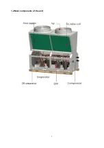
Page 8: ...5 1 2 Main components of the unit ...

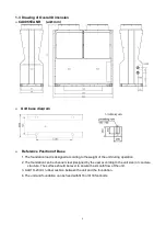
Page 9: ...o the weight of the unit during operation 2 The foundation can be channel steel designed by the user according to the unit size or concrete structure The surface should be level to ensure the smooth flow of the unit 3 Add 10 20mm rubber cushion between the unit and the foundation 4 The unit and foundation can be fixed with Φ16 or Φ18 foot bolts ...

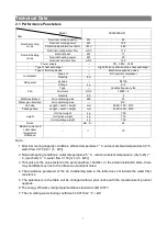
Page 10: ...0 2170 Package Size Length width height mm 2320 830 2270 weight Unit net weight kg 700 Unit gross weight kg 715 Unit operating weight kg 750 Noise dB A 65 Maximum inlet and outlet water temperature difference 10 Note 1 Nominal cooling capacity conditions effluent temperature 7 C outdoor ambient temperature 35 C water flow 0 172 m3 h kW 2 Nominal heating conditions outlet temperature 45 C outdoor a...

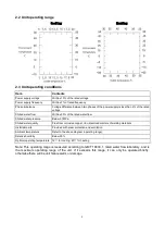
Page 11: ...sure Below 0 7MPa Chilled water quality Free from corrosive copper iron dissolved matters of welding materials Installation site Provided with snow protection and ventilation Ambient temperature Refer to the above diagram operating range Relative humidity Below 90 Optimal operating temperature 12 for cooling 40 for heating Note This operating range is measured according to GB T 18430 1 rated water...

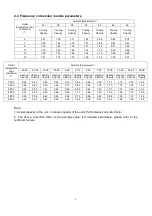
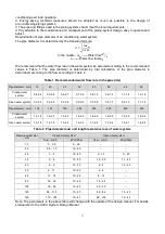
Page 12: ...ting Capcity Heating Capcity Heating Capcity Heating Capcity Heating Capcity Heating Capcity Heating Capcity Heating Capcity Heating Capcity Heating Capcity Heating Capcity Heating Capcity 30 00 0 40 0 47 0 55 0 63 0 73 0 84 0 95 1 09 1 14 1 19 1 32 1 44 35 00 0 38 0 45 0 53 0 60 0 71 0 82 0 93 1 06 1 10 1 15 1 28 1 39 40 00 0 35 0 43 0 51 0 59 0 69 0 80 0 91 1 03 1 07 1 12 1 23 1 34 45 00 0 31 0 ...

Page 13: ...lace to improve the heat exchange The installation position shall have enough strength to withstand the unit weight and the vibration during operation The unit shall not be installed at a place that is dirty oily salty and exposed to a large amount of sulfur gas The chiller unit shall not be installed at such place where flammable gas may leak Because the flammable gas leaked and accumulated aroun...

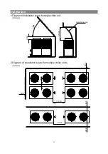
Page 14: ...1 Installation 1500 450 450 450 1500 450 450 Unit mm Unit mm 1 Diagram of installation space for single chiller unit 300 4 8 1000 Guiding device 2 Diagram of installation space for multiple chiller units ...

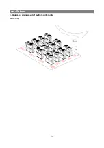
Page 15: ...12 Installation 3 Diagram of arrangement of multiple chiller units Unit mm ...

Page 16: ... water pipe shall be carried out prior to the connection between the pipe and the unit 6 The drain valve on the outlet pipe is self contained manual or automatic exhaust valve shall be set at the highest point of the water circulation system for the normal operation of the unit the valve handle must be removed so that the valve is not adjusted 7 Water quality control Industrial water used as hot w...

Page 17: ... outlet pipe is very low the unit will automatically operate for a period to maintain the temperature of the water system and prevent the water pipe from being frozen so the unit must be energized in winter If the unit is not used in winter drain the water from the water system or fill such anti freezing mixture as ethylene glycol and glycerol into the water system The water filter must be install...

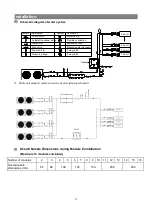
Page 18: ... combined Number of modules 2 3 4 5 6 7 8 9 10 11 12 13 14 15 16 Overall nozzle dimensions mm 65 80 100 125 150 200 250 Symbol Description Check valve Automatic exhaust valve Water filter Stop valve Thermometer Pressure gauge Water pump Flexible connection Expansion tank Electronic water processor 3 way valve 2 way valve Symbol Description Fan coil Fan coil Fan coil Fan coil Heater ...

Page 19: ... long time please discharge water from the unit through the water outlet pipeline connected with the plate heat exchanger of the unit If no water discharge is required for the unit in winter do not cut off the power supply The fan coil in the water system must be provided with a 3 way valve to ensure that the water system is smoothly circulated after the winterizing water pump is started CAUTION T...

Page 20: ...low rate in the pipe m s Pipe diameter mm 12 20 25 32 40 50 65 80 Closed water system 0 4 0 5 0 5 0 6 0 6 0 7 0 7 0 9 0 8 1 0 0 9 1 2 1 1 1 4 1 2 1 6 Open water system 0 3 0 4 0 4 0 5 0 5 0 6 0 6 0 8 0 7 0 9 0 9 1 0 0 9 1 2 1 1 1 4 Pipe diameter mm 100 125 150 200 250 300 350 400 Closed water system 1 3 1 8 1 5 2 0 1 6 2 2 1 8 2 5 1 8 2 6 1 9 2 9 1 6 2 5 1 8 2 6 Open water system 1 2 1 6 1 4 1 8 1...

Page 21: ... or equal to Vmin 310 265 20 25L 3 7 Expansion tank volume calculation The air conditioning water system must be installed with a certain volume of expansion water tank to adapt to the change of system water volume caused by water temperature changes thermal expansion and contraction to prevent the freezing of winter water system and the instability of pump suction pressure at the same time as sys...

Page 22: ...ance of at least 3mm Please install it yourself 4 2 Electric control Control of auxiliary electric heating The start of electrical heating is to provide an auxiliary heating function at low temperatures The inlet and outlet of the auxiliary electric heating are connected in series to the total outlet pipe of the air cooling module unit and the control node for auxiliary electric heating is provide...

Page 23: ...trol contact and the auxiliary electric heating overload protection control contact are provided only 220V output control signal is provided and the passive thermal relay for overload protection is provided by the user The normally closed contact of the passive thermal relay is connected to the overload protection control contact When the current is too large the thermal relay protection is discon...

Page 24: ...0 Host OFF OFF OFF OFF 1 Slave 1 ON OFF OFF OFF 2 Child machine 2 OFF ON OFF OFF 3 Child machine 3 ON ON OFF OFF 4 Slave 4 OFF OFF ON OFF 5 Child machine 5 ON OFF ON OFF 6 Slave 6 OFF ON ON OFF 7 Slave 7 ON ON ON OFF 8 Slave 8 OFF OFF OFF ON 9 Slave 9 ON OFF OFF ON 10 Slave 10 OFF ON OFF ON 11 Slave 11 ON ON OFF ON 12 Slave 12 OFF OFF ON ON 13 Slave 13 ON OFF ON ON 14 Slave 14 OFF ON ON ON 15 Slav...

Page 25: ...ld not exceed 1000m 3 For the communication between the handheld communicator and the host within 300m shielded twisted pair with diameter of 0 75mm2 and above must be used Line to extend the connection between the handheld communicator and the electronic control cabinet 4 For long distance communication connections between 300m and 1000m the A and B communication lines must be shielded twisted pa...

Page 26: ...23 Compressor drive module Capacitor plate Lightning protection board Refrigerant heat sink Reactance ...

Page 27: ... a single compressor Galvanometer confirmation 6 23A 3 Operating current of a single fan Galvanometer confirmation 0 2 3 6A 4 Unit inlet water temperature during cooling operation Thermometer confirmation 8 28 5 Unit outlet water temperature during cooling operation Thermometer confirmation 5 21 6 Unit inlet water temperature during heating operation Thermometer confirmation 24 50 7 Unit outlet wa...

Page 28: ...igerant R410A and lubricant When the system is working properly there is no need to replenish refrigerant or lubricating oil and it is not allowed to charge or replace refrigerant and lubricant If it is necessary to replenish due to leakage please refer to the charging amount specified on the nameplate on the unit 6 2 Maintenance During the use of the unit certain routine inspections must be carri...

Page 29: ...26 maintenance plan can be carried out according to different usage conditions in different regions Description for user self test items check items for professionals ...

Page 30: ...in 60min locked 16 E26 01 02 The system compressor module variable frequency side current detection circuit abnormal 4 times in 60min locked 17 E27 01 02 The system compressor module instantaneous power failure 4 times in 60min locked 18 E28 01 02 Abnormal power supply on the control panel of the system compressor module 4 times in 60min locked 19 E29 01 02 The system compressor module out of step...

Page 31: ...ecoverable 48 E69 01 02 Refrigerant lack protection of system One lock 49 E71 Overtop Temperature difference of in and out water 3 times in 60min locked 50 E72 Running time exceeded One lock 51 E76 01 02 Lower temperature of exhaust temperature sensor of system compressor 3 times in 60min locked 52 E77 01 02 Open circuit or short circuit in oil temperature sensor of system recoverable 53 E78 01 02...

Page 32: ...capacity Check the fan Heating 7 Short circuit found in air circuit Check the cause of short circuit and take troubleshooting Heating 8 Incomplete defrosting Replace the poor 4 way valve or defrosting sensor Heating 3 Too low exhaust pressure 1 Lack of refrigerant Adjust the charge of refrigerant Cooling heating 2 Low suction pressure Refer to Low Suction Pressure Cooling heating 3 Low ambient tem...

Page 33: ...ault in communication of wired controller 1 Incorrect unit numbering Check the unit numbering and correct it Cooling heatin g 2 Incorrect connection of communication wires Check the order of connection of communication wires 3 Damaged PCB Replace the PCB 4 Poor wired controller Replace the wired controller 10 Over current fault of compressor 1 High exhaust pressure and high suction pressure Refer ...

Page 34: ...d Closed recirculation systems may require anti corrosion control including the following for reference only a inhibitors of sodium nitrite borate and organic matter b sodium nitrite borate and silicate c high concentration of complex acid salt pH control d pH and sulfite control e polyphosphites and silicates f alkaline phosphate and sulfite control Since the control of water quality is very diff...

Page 35: ...ater temperature cleaning system etc No need to control Corrosion control 1 1 low concentration of corrosion inhibitors 1 2 anti calcium carbonate scale coating 1 3 pH control 1 4 Suitable manufacturing materials 1 1 High concentration 200 500ppm corrosion inhibitor 1 2 Low concentration 20 30ppm corrosion inhibitor 1 3 pH control 1 4 Suitable manufacturing materials 1 1 high concentration of corr...

Page 36: ...er is earlier However artificial damages e g damages caused by external force operation against rules installation or maintenance by non professional units users improper transport hoisting and engineering installation etc and damages due to external force majeure are not covered by the warranty In such case we will according to relevant regulations charge for repairing or replacing parts at cost ...

Page 37: ......

Page 38: ......

Page 39: ......

Page 40: ......

Reviews: