15
Installation
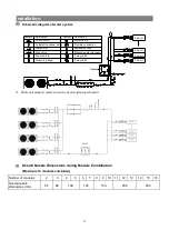
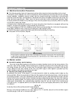
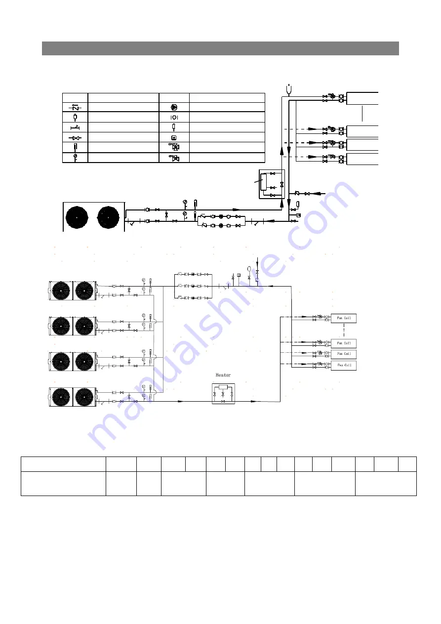
Schematic diagram of water system
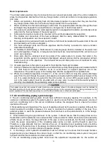
Multi-unit module combined water system installation schematic
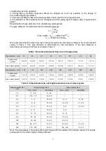
Overall Nozzle Dimensions during Module Combination
(Maximum 16 modules combined)
Number of modules
2
3
4
5
6
7
8
9
10 11
12
13
14
15
16
Overall nozzle
dimensions (mm)
65
80
100
125
150
200
250
Symbol
Description
Check valve
A utomatic exhaust valve
Water filter
S top va lve
Thermometer
P ressure gauge
Wate r pump
Flexible co nnection
E xpansion tank
Electronic water processor
3 -way valve
2 -way valve
Symbol
Description
Fan co il
Fan co il
Fan co il
Fan co il
Heater
Summary of Contents for CA0065EANR
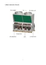
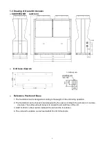
Page 8: ...5 1 2 Main components of the unit ...
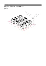
Page 15: ...12 Installation 3 Diagram of arrangement of multiple chiller units Unit mm ...
Page 37: ......
Page 38: ......
Page 39: ......
Page 40: ......

