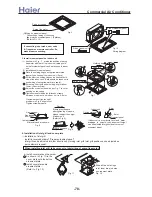
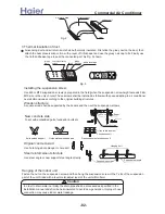
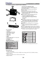

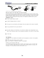

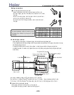
According to the piping method, connect the piping on indoor unit with union of connection pipe.
Arrange the piping as per the wall hole and bind drain hose connecting electric cable and piping
together with polyethylene tape.
Insert the bound piping connecting electric cable and drain hoes through wall hole to connect
with outdoor unit.
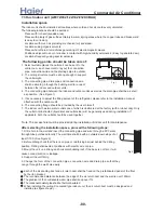
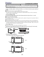
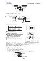
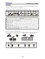
2. Arrangement drain hose
Drain hose shall be placed in under place.
There should be a slope when arrange drain hose. Avoid up and down waves in drain hose.
If humidity is high, drain pipe(especially in room and indoor unit) must be covered with
installation material.
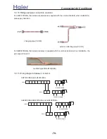
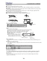
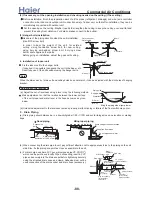
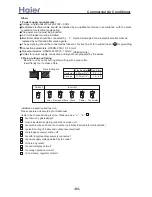
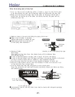
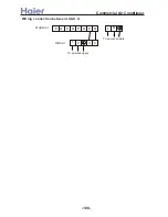
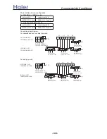
Electric wiring :
When connecting indoor and outdoor wire, check the number on indoor and outdoor terminal
blocks. Terminals of same number and same color shall be connected by the same wire.
Incorrect wiring may damage air conditioner's control or cause operation failure.
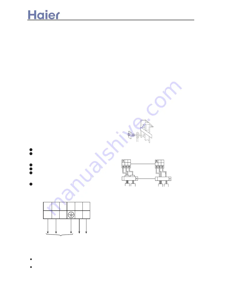
Note:
N
L
R R
W B
Y/G
Q
P
TO POWER SUPPLY
(1PH,220-230,50Hz)
CONNECT TO
OUTDOOR UNIT
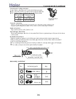
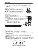
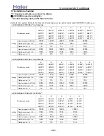
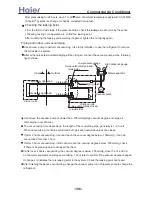
Process of wire connections
1. Loop terminal
After removing the screw, fix the wire ring on the screw, reinsert the screw into the
block terminal and then tighten the screw.
2. Straight terminal
After loosening the screw, inset the wire end into the block terminal and then tighten
the screw. Slightly pull the wire to see if it is tightly fixed.
3. Wire capping
After completion of connection, capping clips must be
applied on the external sleeve of the wires.
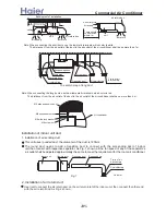
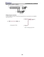
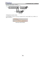
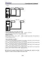
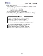
Wiring diagram:
Wiring of indoor unit
Remove air intake screen and take out the front wires.
Connect the wires as specified in the above
methods and diagrams for indoor unit and wire con-
nections.
Properly apply capping clips on the wires.
Replace the air intake screen.
Do not link the connecting and signal wire with the
same cable, a snug space must be maintained
between connecting and signal wires.
Shield of the signal wire should be spot grounded.
Block terminal
Capping clip
Wiring diagram of loop terminals
1(L)
>a__WcU[S^ <[c >a`V[e[a`Wc
-92-
Summary of Contents for AB072XCBAA
Page 21: ... a__WcU S c a V e a Wc AU84NXTBAA 66 33 1 23 4 43 33 61 2 3 160 2 15 3 52 21 ...
Page 138: ... a__WcU S c a V e a Wc AU282XHBAA AU422XIBAA PCB printed diagram 138 ...
Page 141: ... a__WcU S c a V e a Wc AU84NXTBAA PCB printed diagram 141 ...
Page 144: ... a__WcU S c a V e a Wc AB AE AD units PCB printed diagram 144 ...
Page 149: ... a__WcU S c a V e a Wc AF07 142XCBAA PCB printed diagram 149 ...
Page 180: ...MEMO Commercial Air Conditioner ...