

>a__WcU[S^ <[c >a`V[e[a`Wc
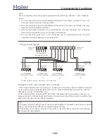
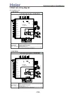
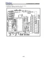
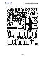
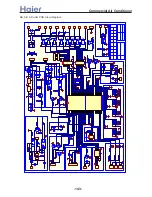
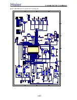
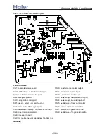
Ports functions:
CN1: communication port between indoor and outdoor of system B
CN2: connection port of ambient temp. and system B coil temp. sensor
CN3: connection port of system A coil temp. sensor
CN4: connection port of system B discharging temp. sensor
CN5: connection port of system A discharging temp. sensor
CN6: communication port between indoor and outdoor of system A
CN8: secondary side output of transformer
CN9: connection port of outdoor motor
CN11: connection port of system A 4-way valve
CN12: connection port of system B 4-way valve
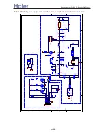
CN14: compulsory operation port; if the side marked with “heat” is connected with the
middle wire, it is compulsory heating; if the side marked with “cool” is connected
with the middle wire, it is compulsory cooling
CN15: time-shorting port, used to shorten 1/60 time
CN16: serial port output, used to connect the device
CN17: system B low pressure switch wire
CN18: system A high pressure switch wire
CN19: system B high pressure switch wire
CN22: system A low pressure switch wire
CN23: to system B unloading valve
CN24: transformer primary side input
CN25: to indoor A1 solenoid valve
CN26: to indoor A2 solenoid valve
CN27: to indoor B1 solenoid valve
CN28: to indoor B2 solenoid valve
CN29: to system A unloading valve
CN31: pre-set control port of oxygen generator
CN32: system A compressor control port
CN33: system B compressor control port
CP1: PCB neutral wire port
CP3, CP4: system A electric heater control port
CP5, CP6: system B electric heater control port
RL7: system A compressor control relay. One port on relay is PCB live wire port
RL8: system B compressor control relay
-139-
Summary of Contents for AB072XCBAA
Page 21: ... a__WcU S c a V e a Wc AU84NXTBAA 66 33 1 23 4 43 33 61 2 3 160 2 15 3 52 21 ...
Page 138: ... a__WcU S c a V e a Wc AU282XHBAA AU422XIBAA PCB printed diagram 138 ...
Page 141: ... a__WcU S c a V e a Wc AU84NXTBAA PCB printed diagram 141 ...
Page 144: ... a__WcU S c a V e a Wc AB AE AD units PCB printed diagram 144 ...
Page 149: ... a__WcU S c a V e a Wc AF07 142XCBAA PCB printed diagram 149 ...
Page 180: ...MEMO Commercial Air Conditioner ...