

;0@^WUec[US^ h[c[`Y V[SYcS_
*
tw
9YXHSSV YRMX
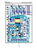
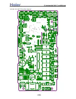
>a__WcU[S^ <[c >a`V[e[a`Wc
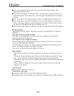
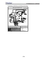
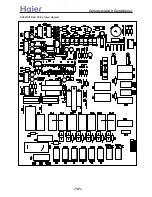
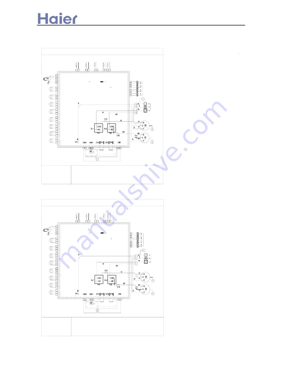
AU282XHBAA:
AU422XIBAA:
Valve A2
0010451214
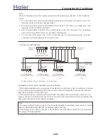
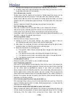
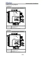
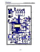
5.LED3 flashing shows that failure occurs.
on 3P side,LED6 will be on,the cooling capacity is 24000-30000BTU/h.
6.CN19 is used to select outdooor capacity:on 5P side,LED6 will be off,and the cooling capacity is 42000BTU/h;
4.Oxygen pump is optional.
1.The communication terminal block to indoor cannot be connected to HT eletricity, or PCB will be damaged.
2.Heater is optional according to different outdoor unit.
3.Valve A1,Valve A2 are not exist in AU302CHBAA.
R:Red Y/G:Yellow/Green
W:White BR:Brown
B:Black BL:Blue
Note:
Transformer
OxygenPump
1 2
Unloading Valve B
4-Way Valve B
3
1
3
2
CN12
2
CN23
1
3
4-Way Valve A
Unloading Valve A
3
1
CN11
2
3
CN29
1
2
Valve B2
Valve B1
CN28
1
2
3
CN27
2
1
3
Heater B
2 3
Heater A
1
3
2
1
Compressor B
Compressor A
To Po
wer
Su
pp
ly
Y/G
2
CN4
Control PCB
LED3
ERR
OUTDOOR WIRING DIAGRAM
G
as
Pi
pi
ng
S
e
ns
or
B
G
as
Pi
pi
ng
Se
ns
or
A
Capacitor
COM
5
Valve A1
CN26
2
1
CN25
2
1
3
CN9
Fan Motor
4
L
3
M
1
2
H
1
2
1
CN5
P
ipi
ng
S
en
so
r A
Te
m
p
. Se
ns
or
Pi
pi
ng
Sen
sor B
1
5p
B1
LED6
CN19
A2
4
CN6
1
3
4
B2
3
2
A1
CN1
2
3p
1
3
2
4
CN2
2
1
CN3
To
Indo
or
Un
it
0010573503
Valve A2
0010451214
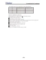
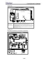
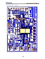
5.LED3 flashing shows that failure occurs.
on 3P side,LED6 will be on,the cooling capacity is 24000-30000BTU/h.
6.CN19 is used to select outdooor capacity:on 5P side,LED6 will be off,and the cooling capacity is 42000BTU/h;
4.Oxygen pump is optional.
1.The communication terminal block to indoor cannot be connected to HT eletricity, or PCB will be damaged.
2.Heater is optional according to different outdoor unit.
3.Valve A1,Valve A2 are not exist in AU302CHBAA.
R:Red Y/G:Yellow/Green
W:White BR:Brown
B:Black BL:Blue
Note:
Transformer
OxygenPump
1 2
Unloading Valve B
4-Way Valve B
3
1
3
2
CN12
2
CN23
1
3
4-Way Valve A
Unloading Valve A
3
1
CN11
2
3
CN29
1
2
Valve B2
Valve B1
CN28
1
2
3
CN27
2
1
3
Heater B
2 3
Heater A
1
3
2
1
Compressor B
Compressor A
To Power S
upp
ly
Y/G
2
CN4
Control PCB
LED3
ERR
OUTDOOR WIRING DIAGRAM
G
a
s Pi
ping
Se
n
so
r B
G
a
s Pipi
ng
Se
n
so
r A
Capacitor
COM
5
Valve A1
CN26
2
1
CN25
2
1
3
CN9
Fan Motor
4
L
3
M
1
2
H
1
2
1
CN5
P
ipin
g
Sens
or A
Te
m
p
. S
en
so
r
Pi
ping
Sen
sor
B
1
5p
B1
LED6
CN19
A2
4
CN6
1
3
4
B2
3
2
A1
CN1
2
3p
1
3
2
4
CN2
2
1
CN3
To
I
ndoo
r
U
ni
t
0010573503
-132-
Summary of Contents for AB072XCBAA
Page 21: ... a__WcU S c a V e a Wc AU84NXTBAA 66 33 1 23 4 43 33 61 2 3 160 2 15 3 52 21 ...
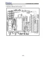
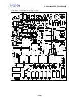
Page 138: ... a__WcU S c a V e a Wc AU282XHBAA AU422XIBAA PCB printed diagram 138 ...
Page 141: ... a__WcU S c a V e a Wc AU84NXTBAA PCB printed diagram 141 ...
Page 144: ... a__WcU S c a V e a Wc AB AE AD units PCB printed diagram 144 ...
Page 149: ... a__WcU S c a V e a Wc AF07 142XCBAA PCB printed diagram 149 ...
Page 180: ...MEMO Commercial Air Conditioner ...