33
Installation and Maintenance Manual, Compact CA
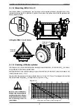
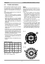
3.1.15 Motors with 2-speed valve
Mounting of 2-speed valve
on CA 50-210
Motor prepared for valve, direction of rotation,
Clockwise = R
C
P
(A-port on motor)
-speed valve
Motor prepared for valve, direction of rotation,
Counter-clockwise = L
C
P
(A-port on motor)
-speed valve
-speed valve
Fig. 3.23
Fig. 3.23a
Motors with -speed function must be ordered
with correct direction of rotation. With wrong
direction, load on the piston will be increased 3
times, which can give overheating of the pistons.
With the high pressure supply connected to A-
port, the motor shaft rotates in the directions
shown by arrows. R-motor rotates clockwise,
and L-motor counter-clockwise, wiewed from
the motor shaft side. If the motor is working
in half displacement, and in not prefered
"direction of rotation", allowed pressure is
max 10 bar (3000 psi).
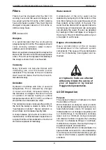
Installation
Remove the protective cover from motor
mounting surface, place the O-rings (included
in delivery) in their proper position on the valve
mounting surface. Use grease to keep O-ring
fixed. Mount valve against the motor with the
ports in corresponding position.
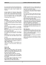
4 pcs 1/ UNC x 17 (5") included in delivery,
strength class 1.9 (ISO 898/1) Tightening
torque: 131 Nm (97 lbf·ft).
*
For Marine applications, use Sicaflex or simi-
lar for corrosion protection.
Direction of rotation see
also page 32.
VTCA 600 will not auto-
matic shift from half to
full displacement at over-
load.
Fig. 3.24
*


