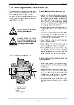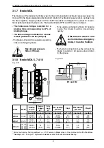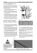
9
Installation and Maintenance Manual, Compact CA
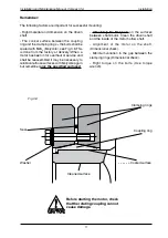
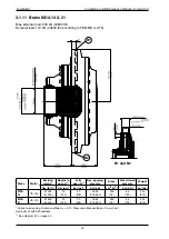
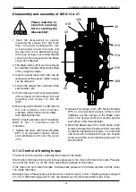
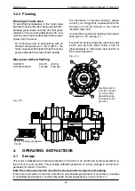
Disassembly of MDA 5, 7 &10.
1. Start the disassembly by slightly loosening
the screws (40). Not more than 1 turn each.
Continue with 1 turn of each screw around
the cover until the pre-load of the Belleville
springs (315)(Cup springs) is zero. After that
the screws can be removed and the Brake
cover (314) lifted off.
. The Brake piston (313) can be removed
by installing an M1 screw in the centre
hole and lifted off by using the screw.
Fig. 3.22
Installation
Note: The M12 screw can not be used to
hold the Brake cover (314) while remo-
ving the screws (40). There is a risk that
the threaded part in the Brake piston
(313) can fail due to big forces when re-
moving the screws.
3. Inner and outer discs (318, 30) can be
removed and the screws (43) holding the
spacer (3xx) in place can be removed.
4. Loosen the screws (43) holding the Disc
centre (30) in place.
Please note that the motor cannot be
pressurised when the brake assembly
is removed.
Please read this instruction
carefully before starting the
disassembly!
3xx
30
43
30
318
40
315
314
313
Connection 1/4" BSP for bearing oil
18 Nm / 13 lbf
.
ft


