15
Installation and Maintenance Manual, Compact CA
Table 3.5
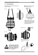
Lifting straps must be
chosen with reliable
saftey margin over the
total weight of the lifted
object.
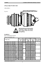
Table 3.6a
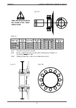
Fig. 3.6
Fig. 3.7
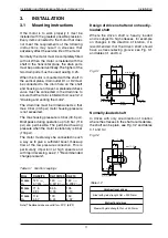
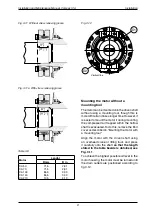
When the motor is placed on a flat surface
such as a floor, it must stand either on its outer
diameter or on the suitably protected end face
of the hollow shaft (see Fig. 3.6 and 3.7).
Standing the motor on a flat surface
Installation
NOTE:
The motor must not be placed on the end
face of the hollow shaft when the coupling is
fitted, since this may cause damage to the
coupling.
When in storage, the motor must always be
placed on the end face to the hollow shaft. It
is also advisable to provide supports at the
mounting surface of the motor; see Fig. 3.7.
Support
Support
Motor
Motor with
shrink disc
Motor with
splines
kg
lb
kg
lb
CA 50
03
447
175
385
CA 70
3
510
05
451
CA 100
310
68
65
583
CA 140
347
763
305
671
CA 210
456
1003
395
869
Torque arm
Weight
kg
lb
TCA 5
TCA 7
TCA 10
TCA 14
1
4
75
65
46
53
165
143
Brake
Weight
kg
lb
MDA 5-10
MDA 14-21
BICA 13
BICA 24
BICA 37
100
30
87
175
10
0
506
191
385
46
Table 3.6b


