Rev.13 5.52.262.00.01.13
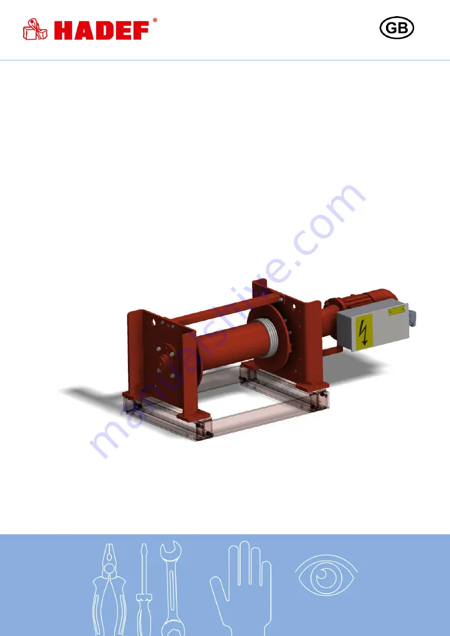
Electric Wire Rope Winch
45/10E + 46/21E
Installation, Operating and Maintenance Instructions
Page 1: ...Rev 13 5 52 262 00 01 13 Electric Wire Rope Winch 45 10E 46 21E Installation Operating and Maintenance Instructions...
Page 2: ...Safety 4 2 1 Warning notice and symbols 4 2 2 Duty of care of the owner 4 2 3 Requirements for the operating personnel 5 2 4 Appropriate use 5 2 5 Basic safety measures 6 3 Transport and Storage 7 3...
Page 3: ...Final decommissioning disposal 28 18 Additional documents 28 18 1 Electric wiring diagrams 28 18 2 Radio control as option 28 1 Information The products meet European Union requirements in particular...
Page 4: ...e is a risk that could lead if it is not avoided to death or severe injury CAUTION This means that there is little risk that could lead if it is not avoided to slight injury or damage to the device or...
Page 5: ...for operation of the units Before starting work the operating personnel must have read the operating and installation instructions especially the chapter Safety Instructions This is especially importa...
Page 6: ...longer period of time visually inspect all components that are important for its function and replace damaged components with new original spare parts Do not use a defective unit listen for abnormal...
Page 7: ...n a covered room If they are used in the open protect the units against the effects of weather such as rain hail snow direct sunshine dust etc we recommend to use a cover in parking position If the de...
Page 8: ...wiring diagram Wire rope exit NOTICE For winches with grooved drum the direction of unwinding the wire rope cannot be changed afterwards 4 3 Functions The lifting gear are operated by pressing the pu...
Page 9: ...acture proof plastic The control cable is fitted with stress relief rope not applicable for radio control 2 step buttons for 2 wire rope speeds Phase sequence monitoring relay All devices with low vol...
Page 10: ...uncharged wire rope Illustration 4 DANGER Disengaging of the drum may never be effected under load and or when current is on 4 4 1 Emergency brake release hoist option Manual emergency brake release...
Page 11: ...5 11 2 7 8 2 7 1 7 4 6 1 1 4 1 1 I 5 m min 4 1 1 0 5 3 1 3 22 5 5 14 3 5 10 2 5 8 2 7 1 7 5 5 1 3 4 5 1 1 3 5 0 9 3 0 8 II m min 9 4 2 3 12 3 0 36 9 20 5 16 4 12 3 10 2 5 8 2 7 1 7 5 5 1 3 4 1 3 5 0 9...
Page 12: ...532 73 67 430 755 60 372 20 4000 M12 87 16 710 1035 532 73 67 430 755 60 372 20 5000 M16 214 16 710 1015 649 68 77 419 724 70 459 25 6300 M16 214 16 710 1015 649 68 77 419 724 70 459 25 8000 M22 530 1...
Page 13: ...ub of the flanged wheel and through the key pocket Pull some centimeters out Wrap it completely round the retainer key 1 and place it back into the key pocket Illustration 8 By pulling the wire rope t...
Page 14: ...e installed in a position centrically to the rope drum In order to ensure correct winding up of the wire rope on the drum the max wire rope deflection angle must not be exceeded maximum wire rope defl...
Page 15: ...can vary depending on the control module Emergency stop Illustration 14 Arrow keys Lifting Lowering Illustration 15 System start optional Illustration 16 Push button functions E Relieved push button...
Page 16: ...Illustration 21 Pull the clutch lever 2 until the ratchet lever 1 locks Lift the ratchet lever 1 The clutch lever 2 moves by spring tension in direction home position Move the drum slowly by hand unti...
Page 17: ...of operation NOTICE Hoists up to 1000 kg capacity and without motor driven trolleys of hoisting unit must be tested by a qualified person before putting into operation for the first time Hoists of 100...
Page 18: ...EF by metioning of serial number 9 2 5 Assignment recommendation of line cross sections and fuses Assignment of line cross sections and fuses must be done acc to VDE0100 For total motor output add all...
Page 19: ...ng installation or adjustment work the wire rope must be tensed by little load or the roller lever must carefully be actuated by hand The switch can also be taken out of service by dismantling the ecc...
Page 20: ...djustment may only be done by a service company authorised by the manufacturer DANGER The factory setting of the overload protection is secured by a seal Any guarantee becomes invalid if this setting...
Page 21: ...ent Illustration 24 Pictures may differ from the actual design 12 6 Pressure roller as option Adjustment Release the screw 1 Turn the square 2 as far until the pressure roller puts enough pressure on...
Page 22: ...antling Sliding block 1 Universal spindle 2 Sliding block receiver 3 Sliding block 4 Laying block 5 Screws For dismantling the sliding block 3 move the laying block 4 centered to the universal spindle...
Page 23: ...ve been determined These conditions have to be written down in the test book The owner user is responsible to make sure that these conditions are observed 13 2 Periodic checks Independently from the r...
Page 24: ...to type 14 Service 14 1 Wire rope Maintenance of the wire rope must be carried out in accordance with the currently valid ISO 4309 CAUTION In case of corrosion cracks or reaching the wear limit the a...
Page 25: ...ipples Recommended lubricant Renolit FEP 2 Illustration 34 DANGER Do not operate the winch during lubrication Permanent lubrication has to be guaranteed 14 4 Disengaging clutch WARNING Work on the dis...
Page 26: ...0 Kl bersynth GH 6 460 Renolit FEP2 Alvania EP2 Unirex EP2 Mobilux EP2 MULTIS EP2 Renolin B10 VG32 Tellus Oil 32 Stabylan 5006 Optimol Viscoleb 1500 Kl beroil 4UH 1 1500 Chain lubricant OKS 451 14 7 L...
Page 27: ...large Re adjust the air gap If the unit is suitable for explosive atmosphere the brake must be returned to the manufacturer for repair Load drops slightly after the operation Electrical equip ment wit...
Page 28: ...all operating material is disposed of in accordance with environmental regulations 17 1 Temporary decommissioning Measures are as above Also read the chapter Transport and storage 17 2 Final decommiss...