


18
5.52.290.00.01.08
12
Maintenance
12.1
General
All monitoring, servicing and maintenance operations are to ensure correct functioning of the equipment;
they must be effected with utmost care.
Only
“qualified persons” may do this work.
Servicing and maintenance work must only be done when the hoist is not loaded.
Records must be kept of all test results and measures taken.
12.2
Monitoring
The monitoring and servicing intervals stated are valid for operation under normal conditions and single-shift
operation. In case of severe operating conditions (e.g. frequent operation with full load) or special
environmental conditions (e.g., heat, dust, etc.), the intervals must be shortened correspondingly
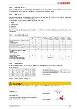
12.3
Brake motor
Brake: 180 V DC
Winch
Type
Brake
Type
Brake
V DC
Nominal brake
moment
Nm
Nominal air gap
mm
air gap
max.
mm
min.
mm
1506
FD 04
105
15
0,3
0,45
1,5 friction lining thickness
1516
FD 15
180
13
0,3
0,45
1,5 friction lining thickness
2306
FD 15
105
26
0,3
0,45
1,5 friction lining thickness
2316
FD 06S
180
40
0,4
0,55
1,5 friction lining thickness
2406
FD 15
105
26
0,3
0,45
1,5 friction lining thickness
2416
FD 06S
180
40
0,4
0,55
1,5 friction lining thickness
3406
FD 15
105
40
0,3
0,45
1,5 friction lining thickness
3416
FD 06
180
100
0,4
0,55
1,5 friction lining thickness
4108
FD 06
180
50
0,4
0,55
1,5 friction lining thickness
5106
FD 06
180
100
0,4
0,55
1,5 friction lining thickness
6105
BFK 20
180
260
0,4
0,6
12 rotor thickness
7104
BFK 20
180
260
0,4
0,6
12 rotor thickness
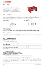
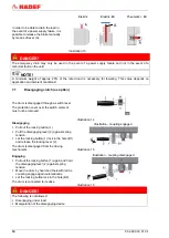
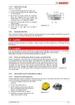
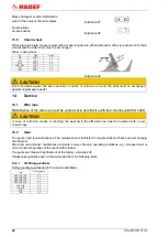
12.3.1
Assembling the brake
1 Insert the retaining ring (1) into the shaft slot.
2 Insert the feather key (2) into the motor shaft.
3 Fix hub (3) with retaining ring (1).
4 Assemble the friction plate (4) if existent.
5 Push the rotor (5) onto the hub (3).
6 Lock the magnet body with the 3 fastening
screws (6).
7
Set air gap “a” (refer to “adjusting the air gap”)
8 Assemble the dust-protection ring (7) if
existent.
9Electric connection
Illustration 17
12.3.2
Disassembly of the brake
Disassembly is performed in reverse order to the assembly.


