


39
Section 4
User Interface
4.1 Instrument
The instrument front panel provides these user interfaces:
•
Touch screen acting as display, touch pad and keyboard. Contrast can be adjusted.
•
LED, showing when the instrument is on.
•
A buzzer which sounds each time the screen is touched, and when an event alarm is set.
Turning Instrument On and Off
There is no power switch on the instrument. The mains must be disconnected to turn the
instrument off. The LED indicates when the instrument is on.
Measurement window
The main (numeric) measurement window continuously displays:
•
Sensor numeric values
•
Measured sensor trends (for the last 10 minutes to last hour)
•
Measured sensor data alarm limits and other events
•
Temperature
4.2 Touch screen
The user interface on the front panel is a 320x240 pixels display with touch screen. To make
navigation user friendly, the interface software is Windows CE based, providing easy selection
through menus.
Touching some items on the display calls a related function, similar to a shortcut.
4.2.1 Function keys on the header bar
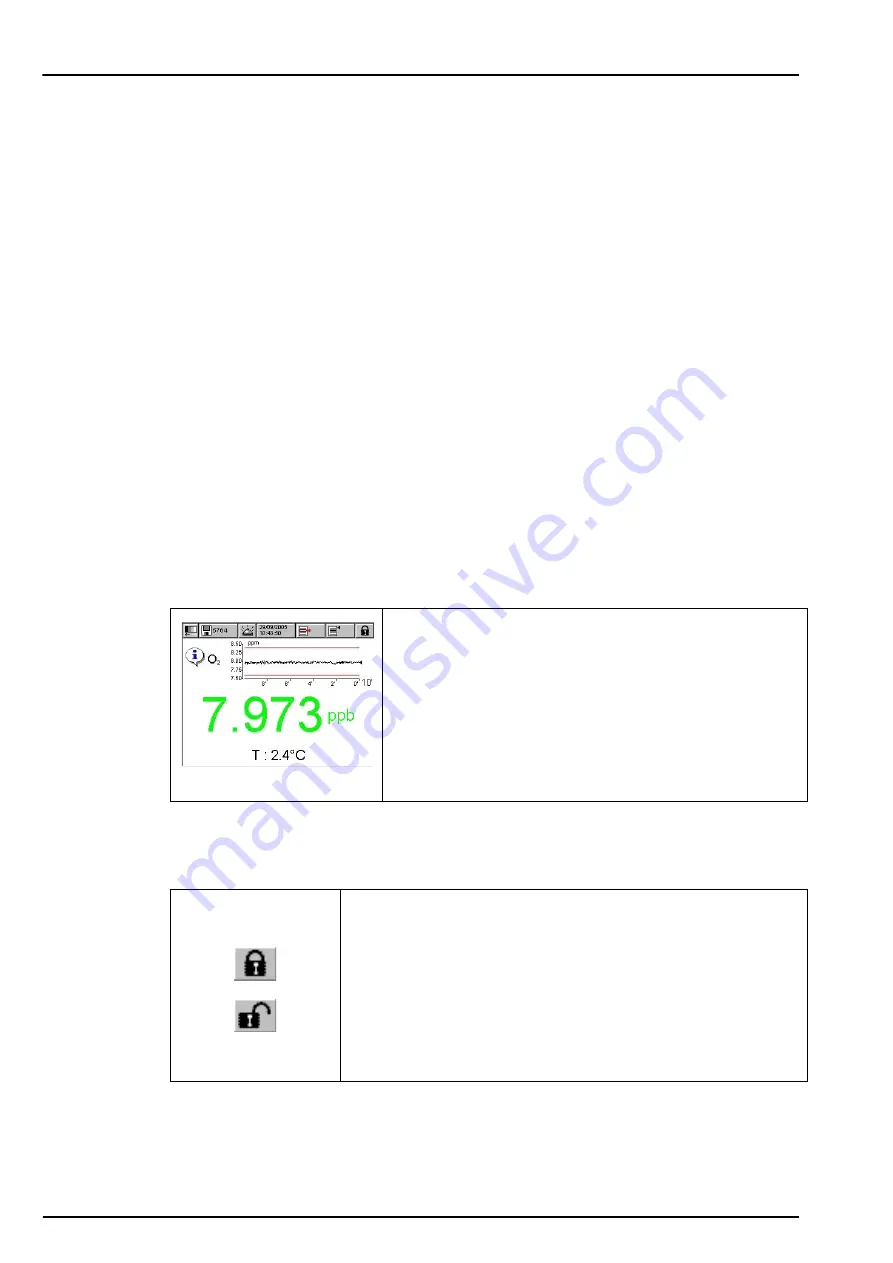
Figure 25 Numeric view
All the measurement, configuration, calibration and "standard
service" routines can be called by pressing buttons and menu
bars on screen.
Measurement display shows one measurement slope.
Display can be configured to only show a sensor
measurement, or to show a parametrized graphic
representation of the last measurements.
Shortcut to the user login window. Pressing this button for more than
2 seconds calls the ID and password window. Refer to
and authorization level on page 42
.
•
Closed padlock indicates that the touch screen is locked.
•
Open padlock indicates that the instrument is in view mode only,
but no user is logged in (level 0).
•
When a user is logged in, this box show the authorization level of
this user as 1, 2, 3 or 4 (4 being the highest, refer to
Summary of Contents for ORBISPHERE K-M1100
Page 5: ...4 Table of Contents ...
Page 19: ...18 Specifications ...
Page 39: ...38 Installation ...
Page 45: ...44 User Interface ...
Page 48: ...47 Section 6 View Menu Figure 33 View menu ...
Page 51: ...50 View Menu ...
Page 52: ...51 Section 7 Measurement Menu Figure 36 Measurement menu ...
Page 59: ...58 Measurement Menu ...
Page 65: ...64 Calibration Menu ...
Page 66: ...65 Section 9 Inputs Outputs Menu Figure 39 Inputs Outputs menu ...
Page 68: ...67 Inputs Outputs Menu 9 4 Analog outputs Figure 40 Analog outputs menu ...
Page 75: ...74 Inputs Outputs Menu ...
Page 91: ...90 Communication Menu ...
Page 94: ...93 Section 12 Products Menu Figure 43 Products menu ...
Page 97: ...96 Global Configuration Menu ...
Page 98: ...97 Section 14 Services Menu Figure 45 Services menu part 1 ...
Page 99: ...98 Services Menu Figure 46 Services menu part 2 ...
Page 107: ...106 Maintenance and Troubleshooting ...
Page 113: ...112 Accessories and Spare Parts ...


