


38
Installation
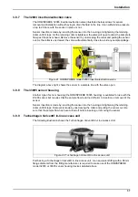
3.8.10 Instrument connections
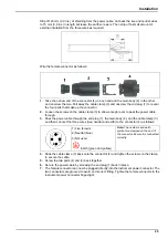
The sensor is supplied with a cable having a LEMO connector at both ends. One end is
attached to the sensor and the other to the instrument.
A red dot can be seen on each LEMO connector and on both the sensor and instrument
sockets. Be sure to line up these red dots when connecting the cable to the sensor and
instrument. The LEMO connector can then simply be pushed into place.
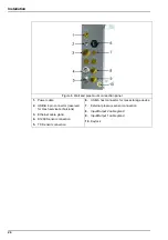
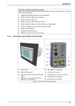
Refer to the illustration of the connector panels for the correct instrument socket to attach the
cable (refer to
for the wall and pipe mount instruments or
for panel instruments).
3.9
Calibration devices
3.9.1
Portable calibration device - K1200 sensor
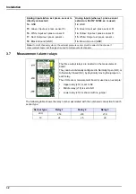
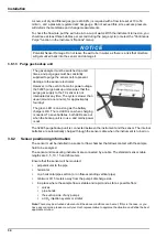
The portable calibration device (part number 33088 illustrated above) is ideal for calibrating the
sensor close to its location in the sample.
The device is designed to hold a 1 liter gas cylinder (as shown above), but is fully compatible for
use with other kinds of gas cylinders. When using other types of gas cylinders, simply connect
the gas supply to the Swagelok connector (number
1
), and make sure that the inlet
gas pressure does
not
exceed 2 bars absolute.
The gas bottle is not supplied and must be purchased locally. To ensure the calibration works
correctly, the calibration gas bottles must be of 99.999% (50) quality or better. Bottles containing
34 liters of compressed gas, with a 5/8-18 UNF (C10) fitting are compatible with the hand-held
calibration device and recommended for this purpose.
Empty gas bottles are easily removed from the device. Simply unscrew the small black screw
(number
2
) a few turns, slide the bottle out of the black plastic holder, and unscrew
the bottle from the pressure reducer. Follow this same procedure in reverse order to install a
new bottle.
Figure 23 Portable calibration device
Summary of Contents for Orbisphere 51 Series
Page 5: ...4 Table of Contents...
Page 19: ...18 Specifications...
Page 48: ...47 Section 6 View Menu Figure 33 View menu...
Page 52: ...51 Section 7 Measurement Menu Figure 36 Measurement menu...
Page 66: ...65 Section 9 Inputs Outputs Menu Figure 40 Inputs Outputs menu...
Page 68: ...67 Inputs Outputs Menu 9 4 Analog outputs Figure 41 Analog outputs menu...
Page 75: ...74 Inputs Outputs Menu...
Page 91: ...90 Communication Menu...
Page 94: ...93 Section 12 Products Menu Figure 44 Products menu...
Page 97: ...96 Global Configuration Menu...
Page 98: ...97 Section 14 Services menu Figure 46 Services menu Part 1...
Page 99: ...98 Services menu Figure 47 Services menu Part 2...
Page 103: ...102 Services menu...


