30
User Interface and Startup
4.2 Instrument startup
Important Note:
The following assumes that the instrument is already fully operational and has
been used for taking measurements. For
first time startup
of the instrument refer to
to ensure additional procedures have been completed successfully for the instrument
to start up without errors occurring during the auto check procedures.
4.2.1 Instrument auto check
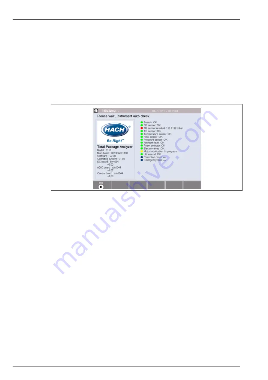
When the instrument is powered
ON
it goes through a number of startup procedures to check all
components are installed and functioning correctly. A number of instrument parameters are also
displayed down the left side of the screen indicating the current software and board versions
installed:
Note:
It is possible (but not recommended) to skip individual checks by pressing the
Skip
button when the
component has the yellow indicator against it to indicate the component check is in progress.
The right side of the screen lists each of the instrument components that are being checked,
and a colored indicator to the left of each component shows the current status:
•
A green indicator means that the component is installed and working correctly
•
A red indicator means that there is a problem with that particular component
•
A yellow indicator means that the component is in the process of being checked
•
A blue indicator means that the component has not yet been checked
If there are errors encountered on startup that mean the instrument cannot function correctly, a
warning screen will be displayed indicating the next course of action.
Important Note:
Once the instrument is switched on you will need to wait until the oxygen
sensor residual value reaches the threshold of
0.1 mbar
. This operation can take as much as two
hours depending on the instrument and sensor conditions prior to startup.
Summary of Contents for ORBISPHERE 6110
Page 1: ...DOC024 52 93009 ORBISPHERE Model 6110 Package Analyzer User Manual 08 2013 Edition 5 ...
Page 2: ......
Page 6: ...4 Table of Contents ...
Page 14: ...12 General Information ...
Page 16: ...14 Specifications 2 2 Instrument dimensions Figure 1 Instrument dimensions ...
Page 28: ...26 Installation ...
Page 34: ...32 User Interface and Startup 4 3 Menu structure overview ...
Page 35: ...33 Section 5 Configuration 5 1 Configuration menu overview ...
Page 46: ...44 Configuration ...
Page 56: ...54 Measurement ...
Page 58: ...56 Analysis ...
Page 70: ...68 Spare Parts and Accessories ...
Page 74: ...72 Material Safety Data Sheets MSDS ...
Page 75: ...73 ...


